We have discuss about Fibre Technology in brief in earlier post. We will be discussing about FC Port Addressing and Fabric Ports. There are certain rules for Port addressing and different ports used for it. Lets summarise point for each in breif.

FC Port Addressing:

  1. FC uses a 3 Byte address identifier.
  2. Dynamically assigned during the LOGIN process.
    Reserved well known addresses used for Fabric, Alias Server, or the Multicast Server - hex'FFFFF0' to hex'FFFFFE'.
  3. hex'FFFFFF' is the Broadcast address.
  4. Arbitrated Loop addresses are 1 Byte long but still use the 3 Byte address identifier.
  5. But still a Global identifier is required and is achieved through a fixed 64 bit value called Name_Identifier or WWN.
  6. Name_Identifier is used to identify nodes (Node_Name), a Port (Port_Name) and a Fabric (Fabric_Name).
  7. Not used to route frames, but used in mapping to ULPs.

FC Ports:

  1. N_Port: Any port on a Node device e.g. a disk, a PC that provides switched interconnections.
  2. Fabric: The entity which interconnects various N_Ports attached to it and is capable of routing frames.
  3. F_Port: A port on a Fabric device that connects to a N_Port.
  4. E_Port: A port on the Fabric that connects through a link to another Fabric port (inter-element expansion port).
  5. G_Port: A Generic Fabric Port capable of behaving either as an E_Port or an F_Port. This behavior is determined at Login time.
  6. L_Port: A N_Port or an F_Port that contains Arbitrated Loop functions associated with Arbitrated Loop topology.
  7. FL_Port: A Fabric Port that may either connect to an N_Port or to an Arbitrated Loop.
  8. GL_Port: A Fabric Port that may connect either to an N_Port, to an E_Port, or to an Arbitrated Loop.
  9. S_Port: A Logical node within the Fabric, capable of communicating either with other Fabric Ports or with N_Ports.

Lets discuss about LUNz/LUN_Z in Operating System specially in CLARiiON environment. We know that what is LUN?? LUN is nothing but logical slice of disc which stands for Logical Unit Number. This terminology comes with SCSI-3 group, if you want to know more just visit www.t10.org and www.t11.org

A SCSI-3 (SCC-2) term defined as "the logical unit number that an application client uses to communicate with, configure and determine information about an SCSI storage array and the logical units attached to it. The LUN_Z value shall be zero." In the CLARiiON context, LUNz refers to a fake logical unit zero presented to the host to provide a path for host software to send configuration commands to the array when no physical logical unit zero is available to the host. When Access Logix is used on a CLARiiON array, an agent runs on the host and communicates with the storage system through either LUNz or a storage device. On a CLARiiON array, the LUNZ device is replaced when a valid LUN is assigned to the HLU LUN by the Storage Group. The agent then communicates through the storage device. The user will continue, however, to see DGC LUNz in the Device Manager.
LUNz has been implemented on CLARiiON arrays to make arrays visible to the host OS and PowerPath when no LUNs are bound on that array. When using a direct connect configuration, and there is no Navisphere Management station to talk directly to the array over IP, the LUNZ can be used as a pathway for Navisphere CLI to send Bind commands to the array.
LUNz also makes arrays visible to the host OS and PowerPath when the host’s initiators have not yet ‘logged in to the Storage Group created for the host. Without LUNz, there would be no device on the host for Navisphere Agent to push the initiator record through to the array. This is mandatory for the host to log in to the Storage Group. Once this initiator push is done, the host will be displayed as an available host to add to the Storage Group in Navisphere Manager (Navisphere Express).
LUNz should disappear once a LUN zero is bound, or when Storage Group access has been attained.To turn on the LUNz behavior on CLARiiON arrays, you must configure the "arraycommpath.

Lets discuss about most important thing in SAN environment ZONING. Zoning is the only way to restrict access for storage to all the host. We will be discussing about Zoning in details.

There are two type of Zoning basically : Hard Zoning and Soft Zoning. Lets first define what is Zoning??

Zoning is nothing but map of host to device to device connectivity is overlaid on the storage networking fabric, reducing the risk of unauthorized access.Zoning supports the grouping of hosts, switches, and storage on the SAN, limiting access between members of one zone and resources in another.

Zoning also restricts the damage from unintentional errors that can corrupt storage allocations or destabilize the network. For example, if a Microsoft Windows server is mistakenly connected to a fabric dedicated to UNIX applications, the Windows server will write header information to each visible LUN, corrupting the storage for the UNIX servers. Similarly, Fibre Channel register state change notifications (RSCN) that keep SAN entities apprised of configuration changes, can
sometimes destabilize the fabric. Under certain circumstances, an RSCN storm will overwhelm a
switch’s ability to process configuration changes, affecting SAN performance and availability for
all users. Zoning can limit RSCN messages to the zone affected by the change, improving overall
SAN availability.

By segregating the SAN, zoning protects applications against data corruption, accidental access,
and instability. However, zoning has several drawbacks that constrain large-scale consolidated
infrastructures.

Lets first discuss what are type of Zoning and pro and cos:

As I have mentioned earlier that Zoning got two types basically you can say three but only 2 types popular in industry.

1) Soft Zoning 2) Hard Zoning 3) Broadcast Zoning

Soft Zoning : Soft zoning uses the name server to enforce zoning. The World Wide Name (WWN) of the elements enforces the configuration policy.
Pros:
- Administrators can move devices to different switch ports without manually reconfiguring
zoning. This is major flexibility to administrator. You don't need to change once you create zone set for particular device connected on switch. You create a zone set on switch and allocate storage to host. You can change any port for device connectivity

Cons:
- Devices might be able to spoof the WWN and access otherwise restricted resources.
- Device WWN changes, such as the installation of a new Host Bus Adapter (HBA) card, require
policy modifications.
- Because the switch does not control data transfers, it cannot prevent incompatible HBA
devices from bypassing the Name Server and talking directly to hosts.

Hard Zoning: - Hard Zoning uses the physical fabric port number of a switch to create zones and enforce the policy.

Pros:

- This system is easier to create and manage than a long list of element WWNs.
- Switch hardware enforces data transfers and ensures that no traffic goes between
unauthorized zone members.
- Hard zoning provides stronger enforcement of the policy (assuming physical security on the
switch is well established).

Cons:
- Moving devices to different switch ports requires policy modifications.

Broadcast Zoning: · Broadcast Zoning has many unique characteristics:
- This traffic allows only one broadcast zone per fabric.
- It isolates broadcast traffic.
- It is hardware-enforced.

If you ask me how to choose the zoning type then it is based on SAN requirement in your data center environment. But port zoning is more secure but you have to be sure that device is not going to change otherwise every time you change in storage allocation you have to modify your zoning.

Generally use in industry is soft zoning but as i have mentioned soft zoning has many cos. So, it is hard to say which one you should use always. So, analyze your datacenter environment and use proper zoning.

Broadcast zoning uses in large environment where are various fabric domain.

Having said that Zoning can be enforced either port number or WWN number but not both. When both port number and WWN specify a zone, it is a software-enforced zone. Hardware-enforced zoning is enforced at the Name Server level and in the ASIC. Each ASIC maintains a list of source port IDs that have permission to access any of the ports on that ASIC. Software-enforced zoning is exclusively enforced through selective information presented to end nodes through the fabric Simple Name Sever (SNS).

If you know about switch then you must notice that in Cisco we have FCNS database and Brocade Name Server. Both are for same purpose to store all the information about port and other. FCNS is stand for Fibre Channel Name Server.

There are plenty of thing on Switch itself to protect your SAN environment. Each vendor comes with different security policy. Zoning is the basic thing in order to secure your data access.

Hope this info will be useful for beginner. Please raise a comment if you want to know specific things.

I have been receiving mail to write on basic storage topic rather than only EMC. Here is first basic thing to know about FC technology.

Fibare Channel is nothing but just a medium to connect host and shared storage. When we talk about SAN first things comes in mind about Fibre Channel.

Fibre Channel is serial data transfer interface intended for connecting shared storage to computer. Where storage is not connected physically to host.

Why FC is most important in SAN? Because FC gives you high speed through the following process:

1) Networking and I/O Protocol such as SCSI command, are mapped to FC construct
2) Encapsulate and transported with FC frame.
3) With this, the hight speed transfer of multiple protocol is possible over same physical interface.

FC operate over copper wire or optical fibre at the rate upto 4GB/s and upto 10GB/s when used as ISL (E - Port) on supported switch.
At the same time, latency is kept very low, minimizing the delay between data requests and deliveries. For example, the latency across a typical FC switch is only a few microseconds. It is this combination of high speed and low latency that makes FC an ideal choice for time-sensitive or transactional processing environments.

These attributes also support high scalability, allowing more storage systems and servers to be interconnected.Fibre Channel is also supports a variety of topologies, and is able to operate between two devices in a simple point-to-point mode, in an economical arbitrated loop to connect up to 126 devices, or (most commonly) in a powerful switched fabric providing simultaneous full-speed connections for many thousands of devices. Topologies and cable types can easily be mixed in the same SAN.

FC is the most important in building SAN, it gives us flexibility to use protocol like FCP, FICON, IP (iSCSI, FCIP, iFCP) and uses block type data transfer.

if we want to define what is FC - Fibre Channel is a storage area networking technology designed to interconnect hosts and shared storage systems within the enterprise. It's a high-performance, high-cost technology. iSCSI is an IP-based storage networking standard that has been touted for the wide range of choices it offers in both performance and price.

Fibre Channel technology is a block-based networking approach based on ANSI standard X3.230-1994 (ISO 14165-1). It specifies the interconnections and signaling needed to establish a network "fabric" between servers, switches and storage subsystems such as disk arrays or tape libraries. FC can carry virtually any kind of traffic.

However, there are some recognized disadvantages to FC. Fibre Channel has been widely criticized for its expense and complexity. A specialized HBA card is needed for each server. Each HBA must then connect to corresponding port on a Fibre Channel Switch. creating the SAN "fabric." Every combination of HBA and switch port can cost thousands of dollars for the storage organization. This is the primary reason why many organizations connect only large, high-end storage systems to their SAN. Once LUNs are created in storage, they must be zoned and masked to ensure that they are only accessible to the proper servers or applications; often an onerous and error-prone procedure. These processes add complexity and costly management overhead to Fibre Channel SANs.

When running inq or syminq, you'll see a column titled Ser Num. This column has quite a bit of information hiding in it.

An example syminq output is below. Your output will differ slightly as I'm creating a table from a book to show this; I don't currently have access to a system where I can get the actual output just yet.

Device
Product Device
------------------------ ---------- ---------------------- ----------------------
Name Type Vendor ID Rev Ser Num Cap(KB)
---------------- ----- -------- --------- ------- --------- --------
/dev/dsk/c1t0d0
EMC SYMMETRIX 5265 73009150 459840
/dev/dsk/c1t4d0 BCV EMC SYMMETRIX 5265 73010150 459840
/dev/dsk/c1t5d0 GK EMC SYMMETRIX 5265 73019150 2880
/dev/dsk/c2t6d0 GK EMC SYMMETRIX 5265 7301A281 2880

Using the first and last serial numbers as examples, the serial number is broken out as follows:

73 Last two digits of the Symmetrix serial number
009 Symmetrix device number
15 Symmetrix director number. If <= 16, using the A processor
0 Port number on the director


73 Last two digits of the Symmetrix serial number
01A Symmetrix device number
28 Symmetrix director number. If > 16, using the B proccessor on board: (${brd}-16).
0 Port number on the director

So, the first example, device 009 is mapped to director 15, processor A, port 0 while the second example has device 01A mapped to director 12, processor B, port 0.


Even if you don't buy any of the EMC software, you can get the inq command from their web site. Understanding the serial numbers will help you get a better understanding of which ports are going to which hosts. Understanding this and documenting it will circumvent hours of rapturous cable tracings.

SYMCLI BASE Commands

symapierr - Used to translate SYMAPI error code numbers into SYMAPI error messages.
symaudit - List records from a symmetrix audit log file.
symbcv - Perform BCV support operations on Symmetrix BCV devices.
symcfg - Discover or display Symmetrix configuration information. Refresh the
host's Symmetrix database file or remove Symmetrix info from the file. Can also
be used to view or release a 'hanging' Symmetrix exclusive lock.
symchg - Monitor changes to Symmetrix devices or to logical objects stored on Symmetrix
devices.
symcli - Provides the version number and a brief description of the commands included in
the Symmetrix Command Line
symdev - Perform operations on a device given the device's Symmetrix name. Can also be
used to view Symmetrix device locks.
symdg - Perform operations on a device group (dg).
symdisk - Display information about the disks within a Symmetrix.
symdrv - List DRV devices on a Symmetrix.
symevent - Monitor or inspect the history of events within a Symmetri
symgate - Perform operations on a gatekeeper device.
symhost - Display host configuration information and performance statistics.
syminq - Issues a SCSI Inquiry command on one or all devices. Interface.
symlabel - Perform label support operations on a Symmetrix device.
symld - Perform operations on a device in a device group (dg).
symlmf - Registers SYMAPI license keys.
sympd - Perform operations on a device given the device's physical name.
symstat - Display statistics information about a Symmetrix, a Director, a device group, or a
device.
symreturn - Used for supplying return codes in pre-action and post-action script files.

SYMCLI CONTROL Commands

symacl - Administer symmetrix access control information.
symauth - Administer symmetrix user authorization information.
symcg - Perform operations on an composite group (cg).
symchksum - Administer checksum checks when an Oracle database writes
data files on Symmetrix devices.
symclone - Perform Clone control operations on a device group or on a
device within the device group.
symconfigure - Perform modifications on the Symmetrix configuration.
symconnect - Setup or Modify Symmetrix Connection Security functionalit
symmask - Setup or Modify Symmetrix Device Masking functionality.
symmaskdb - Backup, Restore, Initialize or Show the contents of
the device masking database.
symmir - Perform BCV control operations on a device group or on a
device within the device group.
symoptmz - Perform Symmetrix Optimizer control operations.
symqos - Perform Quality of Service operations on Symmetrix Devices
symrdf - Perform RDF control operations on a device group or on a
device within the device group.
symreplicate - Perform automated, consistent replication of data given
a pre-configured SRDF/Timefinder setup.
symsnap - Perform Symmetrix Snap control operations on a device
group or on devices in a device file.
symstar - Perform SRDF STAR management operations.
symrcopy - Perform Symmetrix Rcopy control operations on devices in
a device file.

SYMCLI SRM(Mapping) Commands

symhostfs - Display information about a host File, Directory,
or host File System.
symioctl - Send IO control commands to a specified application.
symlv - Display information about a volume in Logical Volume
Group (vg).
sympart - Display partition information about a host device.
symrdb - Display information about a third-party Relational
Database.
symrslv - Display detailed Logical to Physical mapping information
about a logical object stored on Symmetrix devices.
symvg - Display information about a Logical Volume Group (vg).

MDS Interoperability Mode Limitations

When a VSAN is configured for the default interoperability mode, the MDS 9000 Family of switches is limited in the following areas when interoperating with non-MDS switches:

• Interop mode only affects the specified VSAN. The MDS 9000 switch can still operate with full functionality in other non-interop mode VSANs. All switches that partake in the interoperable VSAN should have that VSAN set to interop mode, even if they do not have any end devices.

• Domain IDs are restricted to the 97 to 127 range, to accommodate McData's nominal restriction to this same range. Domain IDs can either be set up statically (the MDS 9000 switch will only accept one domain ID; if it does not get that domain ID, it isolates itself from the fabric), or preferred (if the MDS 9000 switch does not get the requested domain ID, it takes any other domain ID).

• TE ports and PortChannels cannot be used to connect an MDS 9000 switch to a non-MDS switch. Only E ports can be used to connect an MDS 9000 switch to a non-MDS switch. However, TE ports and PortChannels can still be used to connect an MDS 9000 switch to other MDS 9000 switches, even when in interop mode.

• Only the active zone set is distributed to other switches.

• In MDS SAN-OS Release 1.3(x), Fibre Channel timers can be set on a per VSAN basis. Modifying the times, however, requires the VSAN to be suspended. Prior to SAN-OS Release 1.3, modifying timers required all VSANs across the switch to be put into the suspended state.

• The MDS 9000 switch still supports the following zoning limits per switch across all VSANs:

– 2000 zones (as of SAN-OS 3.0, 8000 zones)

– 20000 aliases

– 1000 zone sets

– 20000 members

– 8000 LUN members

– 256 LUN members per zone/alias

Brocade Interoperability Mode Limitations

When interoperability mode is set, the Brocade switch has the following limitations:

• All Brocade switches should be in Fabric OS 2.4 or later.

• Interop mode affects the entire switch. All switches in the fabric must have interop mode enabled.

Msplmgmtdeactivate must be run prior to connecting the Brocade switch to either an MDS 9000 switch or a McData switch. This command uses Brocade proprietary frames to exchange platform information. The MDS 9000 switch and McData switches do not understand these proprietary frames, and rejection of these frames causes the common E ports to become isolated.

• Enabling interoperability mode is a disruptive process to the entire switch. It requires the switch to be rebooted.

• If there are no zones defined in the effective configuration, the default behavior of the fabric is to allow no traffic to flow. If a device is not in a zone, it is isolated from other devices.

• Zoning can only be done with pWWNs. You cannot zone by port numbers or nWWNs.

• To manage the fabric from a Brocade switch, all Brocade switches must be interconnected. This interconnection facilitates the forwarding of the inactive zone configuration.

Domain IDs are restricted to the 97 to 127 range to accommodate McData's nominal restriction to this same range.

• Brocade WebTools will show a McData switch or an MDS 9000 switch as an anonymous switch. Only a zoning configuration of the McData switch or the MDS 9000 switch is possible.

• Private loop targets will automatically be registered in the fabric using translative mode.

• Fabric watch is restricted to Brocade switches only.

• The full zone set (configuration) is distributed to all switches in the fabric. However, the full zone set is distributed in a proprietary format, which only Brocade switches accept. Other vendors reject these frames, and accept only the active zone set (configuration).

• The following services are not supported:

– The Alias Server


What are the CLARiiON SAN fan-in and fan-out configuration rules?"

Fan-In Rule: A server can be zoned to a maximum of four storage systems.

Fan-Out Rule:

  • For FC5300 with Access Logix software - 1 - 4 servers (eight initiators) to 1 storage system.
  • For FC4500 with Access Logix - 15 servers to 1 storage system; each server with a maximum of one (single) path to an SP.
  • For FC4700 with Base or Access Logix software 8.42.xx or higher - 32 initiators per SP port for a maximum of 128 initiators per FC4700. Each port on each SP supports 32 initiators. Ports 0 and 1 on each SP in a FC4700 handles server connections. Port 1 on each SP in a FC4700 with MirrorView also handles remote mirror connections. In a remote mirror configuration, each path between SP A port 1 on one storage system and SP A port 1 on another storage system counts as one initiator for each port 1. Likewise, each path between SP B port 1 on one storage system and SP B port 1 on another storage system counts as one initiator for each port 1.
  • For FC4700 with Base or Access Logix software 8.41.xx or lower - 15 servers to 1 storage system; each server with a maximum of one (single) path to an SP.
  • For CX200 - 15 initiators per SP, each with a maximum of one (single) path to an SP; maximum of 15 servers.
  • Fan-Out for CX300 - 64 initiators per SP for a maximum of 128 initiators per storage system.
  • For CX400 - 32 initiators per SP port for a maximum of 128 initiators per CX400. Each port on each SP supports 32 initiators. Ports 0 and 1 on each SP in a CX400 handles server connections. Port 1 on each SP in a CX400 with MirrorView also handles remote mirror connections. In a remote mirror configuration, each path between SP A port 1 on one storage system and SP A port 1 on another storage system counts as one initiator for each port 1. Likewise, each path between SP B port 1 on one storage system and SP B port 1 on another storage system counts as one initiator for each port 1.
  • Fan-Out CX500 - 128 initiators per SP and maximum of 256 initiators per CX500 available for server connections. Ports 0 and 1 on each SP handle server connections. Port 1 on each SP in a CX500 with MirrorView/A or MirrorView/S enabled also handles remote mirror connections. Each path used in a MirrorView or SAN Copy relationship between two storage system counts as an initiator for both storage systems.
  • For CX600 - 32 initiators per SP port and maximum of 256 initiators per CX600 available for server connections. Ports 0, 1, 2, and 3 on each SP in any CX600 handle server connections. Port 3 on each SP in a CX600 with MirrorView also handles remote mirror connections. In a remote mirror configuration, each path between SP-A port 3 on one storage system and SP-A port 3 on another storage system counts as one initiator for each port 3. Likewise, each path between SP-B port 3 on one storage system and SP-B port 3 on another storage system counts as one initiator for each port 3.
  • Fan-Out CX700 - 256 initiators per SP and maximum of 512 initiators per CX700 available for server connections. Ports 0, 1, 2, and 3 on each SP in any CX700 handle server connections. Port 3 on each SP in a CX700 with MirrorView/A or MirrorView/S enabled also handles remote mirror connections. Each path used in a MirrorView or SAN Copy relationship between two storage system counts as an initiator for both storage systems
  • An initiator is any device with access to an SP port. Each port on each SP supports 32 initiators. Check with your support provider to confirm that the above rules are still in effect.

Save Set Staging:

Save set staging is a process of transferring data from one storage medium to another. Staging reduces the time it takes to complete a backup by directing the initial backup to a high performance file type or adv_file device. The data can then be staged to a storage medium, freeing up the disk space. Any volume type, such as Default, Index Archive, or Default Clone, can be staged. Staging is particularly well suited for data that has been backed up on file type or adv_file devices. Staging allows the occupied disk space on file type or adv_file devices to be reclaimed so that the disk space can be used for other purposes. Use staging to move the data to more permanent storage, such as an optical or tape volume, or even another, lower-priority device. Staging also allows data to be moved off the device outside the backup period, ensuring that sufficient disk space is available for the next backup session. Additional licencing may be required.

You can create, edit, and delete staging policies as you can for other NetWorker resources. As part of the client setup, the use of a staging device can be selected for each pool (or set of pools) for backup, archive, and migration. The files are retained for the specified time in the disk staging pool before being moved to a tape device or optical disk. Any number of devices can be in the staging pool, and a save set can be staged as many times as required, for example to disk, to optical disk, to a local tape device, and to a remote tape device. Also, a volume can be staged to a second volume, and then that data on the second volume can be staged back to the first volume.

The staging process is driven by one of the following events:

- As part of an automatic process, such as keeping the save set for 30 days on the staging device before staging the data to the next device.

- As part of an event driven process, such as when available space in the staging pool drops below a set threshold. When this happens, the oldest save sets are moved first, until available space reaches the upper threshold that has been set.

- As part of an administrator initiated process, such as allowing the administrator to either reset the threshold and kick off staging or manually select save sets to stage.

When you enable a staging policy, the NetWorker server creates a clone of the save set you specify on a clone volume of the medium you specify. After the save set is staged, the save set is deleted from the filesystem to free the space.

The NetWorker server tracks the location of the save set in the media database. The retention policy for the save set does not change when the data is staged. If the file type volume is on a storage node that is running NetWorker software 6.1 or earlier, the tape is not automatically marked appendable after the staging operation.

There is available WWN decoder tool for EMC but I am going to discuss how to decode manually?
Each Symmetrix SAF port, RAF port, EF ficon port or DAF port (DMX only) has a unique worldwide name (WWN). The WWN is associated with the Tachyon chip on the director. It was intended to remain unique per director so that the director can be accessed on a storage area network. The Symmetrix SAF/RAF/DAF/EF WWN is dependent on the Symmetrix serial number, the director number, the processor letter, and the port on the processor. When the SAF/RAF/DAF is inserted into the Symmetrix, it discovers the Symmetrix serial number and slot number and the WWNs are set for the ports on the director.

Symm 4/4.8/5 (2-port or 4-port) Fibre Channel front directors, the WWN breakdown are as follows:

The director WWN (50060482B82F9654) can be broken down (in binary) as follows:

First 28 Bits (from the left, bits 63-36, binary) of WWN are assigned by the IEEE (5006048, the vendor ID for EMC Symmetrix)

5006048 2 B 8 2 F 9 6 5 4
0010 1011 1000 0010 1111 1001 0110 0101 0100

0 A E 0 B E 5 9 -----------------------> AE0BE59 hex = 182500953 Symm S/N

Bits 36 through 6 represent the Symmetrix serial number; the decode starts at bit 6 and works up to 36 to create the serial number. This is broken down as illustrated above.

The least signifigant 6 bits (bits 5 through 0) can be decoded to obtain the Symmetrix director number, processor and port. Bit 5 is used to designate the port on the processor (0 for A, 1 for B). Bit 4, known as the side bit, is used to designate the processor (0 for A, 1 for B). The least signifigant 4 bits, 3 through 0, represent the Symm slot number.


01 0100 = 14 hex -----> director 5b port A

In review, this WWN represents EMC Symmetrix serial number 182500953, director 5b port A

For Symm DMX product family (DMX-1/2/3), the WWN breakdown are as follows:

The director WWN (5006048ACCC86A32) can be broken down (in binary) as follows:

Again, like Symm 4/5, the first 28 bits (63-36) are assigned by the IEEE

5006048 A C C C 8 6 A 3 2

1010 1100 1100 1100 1000 0110 1010 0011 0010

B 3 3 2 1 A 8 ----------------------> B3321A8 hex = 187900328 Symm S/N

Bit 35 is now known as the 'Half' bit and is now used to decode which half the processor/port lie on the board.

Bits 34 through 6 represent the serial number; the decode starts at bit 6 and works up to bit 34 to create the serial number. This is broken down as illustrated above.

In conjunction with bit 35, the last 6 bits of the WWN represent the director number, processor and port. Bit 35, the 'Half' bit, represents either processor A and B, or C and D (0 for A and B, 1 for C and D). Bit 5 again represents the port on the processor (0 for A, 1 for B). Bit 4, the side bit, again represents the processor but with a slight change (if 0 then port A or C, if 1 then port B or D, depending on what the half bit is set to). The last 4 bits, 3 through 0, represent the Symm slot number.

1 11 0010 -------> half bit = 1 (either processor C or D), port bit = 1 (port B), side bit = 1 (because half = 1, looking at C and D processors only, side = 1 now means processor D)
0010 hex = 2 decimal (slot 2 or director 3)

In review, the WWN of 5006048ACCC86A32 represents EMC Symmetrix serial number 187900328, director 3d port B


Generally we never give thought about VCMDB database once we initialize first time. It does make sense when you messup or did some thing disaster. This database is most impppppportaaaaaaant for DMX. Once you loose this database means you can't get DMX configuration back at any cost. So, I am discussing different type of VCMDB on DMX.

We can now support up to 16,000/64000 addressable devices enginuity 5771 onward and therefore the Volume Control Manager Database needs to be physically larger. At 5670, as per EMC recommend CE's were encouraged to create 96 cylinder (minimum) VCMDB during new installs. This was to cater for future upgrades to 5671.

To summarize the VCMDB type applicable to DMX :

Type 3 - this can cater for 32 fibre or iSCSI initiators per port. Introduced with Enginuity 5669 and requires a 24 cylinder (minimum) VCMDB and Solutions Enabler v5.2.

Type 4 - this can cater for 64 fibre or 128 iSCSI initiators per port. Introduced with Enginuity 5670 and requires a 48 cylinder (minimum) VCMDB and Solutions Enabler v5.3.

• Type 5 - this can support 64 fibre or 128 iSCSI initiators per port AND cater for 16,000 devices. Introduced with Enginuity 5671 and requires a 96 cylinder (minimum) VCMDB and Solutions Enabler v6.0. (Note: without a type 5 96cyl VCMDB and SE 6.0 you will be restricted to 8192 logical volumes as in 5670).

Type 6 - this can support 128 fibre or 256 iSCSI initiators per port AND cater for 32,000 devices available on DMX-3 with Enginuity 5771 (at GA release). Currently the Type 6 database (at latest Enginuity 5771 with Solution Enabler 6.0 and above) will cater for 256 fibre or 512 iSCSI initiators and 64,000 logical devices.

What is requirement for Type 5:

The three requirements for a Type 5 VCM database on DMX (and support for up to 16,000 customer addressable volumes) is a correctly configured 96 cylinder VCMDB device, Enginuity 5671 and Solutions Enabler v6.0 or above. Note that the VCMBD “type” reflects the internal data structure of the Volume Control Manager Database. Therefore a 96 cylinder VCMDB size does NOT mean that you have a Type 5 VCMDB.

Note:
• At 5670 with a 48 cylinder VCMDB it is still type 4.
• At 5670 with a 96 cylinder VCMDB it is still type 4.
• At 5670 with a 96 cylinder VCMDB and SE 6.0 it is still type 4 - do not try to convert the database using the SYMCLI (EMC do not support more than 8192 logical volumes at 5670).
• At 5671 with a 48 cylinder VCMDB and SE 6.0 it is still type 4 - the VCMDB is NOT physically large enough.
• At 5671 with a 96 cylinder VCMDB and SE 5.5 it is still type 4 - the VCMDB is large enough but SE 5.5 does not support the Type 5 database.
• At 5671 with a 96 cylinder VCMDB and SE 6.0 it is a type 5 database - if you have run the “symmaskdb convert -vcm_type 5” command. Be aware that if you convert from a lower type database to a higher type, any hosts running a Solutions Enabler version that does not support the higher VCMDB type will NOT be able to access the "new" database.
• At 5771 (DMX-3) the VCMDB data now resides in the SFS volumes. At 5771 the VCMDB should be configured the SAME size as a standard FBA gatekeeper (this can be 3 cylinders due to the 64KB track size but 6 cylinder, as recommended in some guides, is also perfectly acceptable) but it must still be assigned the VCM fibre gatekeeper status. Note that the VCMDB "gatekeeper" on DMX-3 is no longer shown as "write disabled" (it is now a "gatekeeper" rather than a physical volume used for physical storage - the Volume Control Manager data is protected and stored on the internal SFS volumes).
• Note that Enginuity 5771 will ONLY support a Type 6 VCM database (again the data is resident on the SFS volumes). This re-location of the physical database to the SFS volumes caters for the increased host connectivity AND the increase in logical volumes supported with DMX-3.

I am going to discuss about TimeFinder BCV Split operation where Host running on Oracle Database. This split operation is different from normal BCV split operation. There are differences in command as well. Thats reason I am putting steps for this:

The following steps describes splitting BCV devices that hold a database supporting a host running an Oracle database. In this case, the BCV split operation is in an environment without PowerPath or ECA. The split operation described here suspends writes to a database momentarily while an instant split occurs. After an establish operation and the standard device and BCV mirrors are synchronized, the BCV device becomes a mirror copy of the standard device. You can split the paired devices to where each holds separate valid copies of the data, but will no longer remain synchronized to changes when they occur.

The Oracle database is all held on standard and BCV devices assigned to one Oracle device group.

1) Check device status on the database BCVs
To view and check status of the database BCV pairs, use the following form:

symmir –g DgName query

Check the output to ensure all BCV devices listed in the group are in the synchronized state

2) Check and set the user account

For SYMCLI to access a specified database, set the SYMCLI_RDB_CONNECT environment variable to the username and password of the system administrator’s account. The export action sets this variable to a username of system and a password of manager, allowing a local connection as follows:

export SYMCLI_RDF_CONNECT=system/manager

The ORACLE_HOME command specifies the location of the Oracle binaries and the ORACLE_SID command specifies the database instance name as follows:

export ORACLE_HOME=/disks/symapidvt/oraclhome/api179
export ORACLE_sid=api179


You can test basic database connectivity with the symrdb command as follows:

symrdb list –type oracle

3) Backup the database

For safety, perform a database hot backup. For example:

symioctl begin backup –type oracle –nop


4) Freeze the database
For safety, perform a freeze on the database I/O. For example:

symioctl freeze –type oracle –nop

This command suspends writes to the Oracle database.

5) Split all BCV devices in the group
To split all the BCV devices from the standard devices in the database device group, enter:

symmir –g oraclegrp split –instant -noprompt

Make sure the split operation completes on all BCVs in the database device group.

6) Thaw the database to resume I/O
To allow writes to the database to resume for normal operation, enter:

symioctl thaw –type oracle –nop

7) End the backup
To terminate the hot backup mode, enter the following command:

symioctl end backup –type oracle –nop

Vendor Worldwide Names WWN :


Twenty-four of the sixty-four bit •World Wide Name• must be unique for every vendor. A partial listing of those vendors most familiar to EMC with regard to Symmetrix Fibre Channel connectivity.

If decoding a HBA WWN, then issue an 8f, command to view the WWN in the FA login table. Bytes 1-3 of the World Wide Names contain the unique vender codes. Note that if there is a switch connected between the FA and the host bus adapter, then the name and fabric servers of the switch will login to the FA. These WWNs can be decoded in the same way as the HBA WWNs.

In the following example the unique vendor code is 060B00, this indicates that the HBA attached was supplied by Hewlett Packard.

UTILITY 8F -- SCSI Adapter utility : TIME: APR/23/01 01:23:30
------------------------------------

HARD LOOP ID : 000 (ALPA=EF) LINK STATE : ONLINE: LOOP
CHIP TYPE/REV: 00/00 Q RECS TOTAL: 3449 CREDIT: 0 RCV BUFF SZ: 2048

IF FLAGS : 01/ TAGD/NO LINK/NO SYNC/NO WIDE/NO NEGO/NO SOFT/NO ENVT/NO CYLN
IF FLAGS1: 08/NO PBAY/NO H300/NO RORD/ CMSN/NO QERR/NO DQRS/NO DULT/NO SUNP
IF FLAGS2: 00/NO SMNS/NO DFDC/NO DMNQ/NO NFNG/NO ABSY/NO SQNT/NO NRSB/NO SVAS
IF FLAGS3: 00/NO SCI3/NO ..../NO ..../NO ..../NO ..../NO ..../NO ..../NO ....

FC FLAGS : 57/ ARRY/ VOLS/ HDAD/NO HDNP/ GTLO/NO PTOP/ WWN /NO VSA
FC FLAGS1: 00/NO VCM /NO CLS2/NO OVMS/NO ..../NO ..../NO ..../NO ..../NO ....
FC FLAGS2: 00/NO ..../NO ..../NO ..../NO ..../NO ..../NO ..../NO ..../NO ....
FC FLAGS3: 00/NO ..../NO ..../NO ..../NO ..../NO ..../NO ..../NO ..../NO ....

HOST SID PORT NAME (WWN) NODE NAME RCV BUF CREDIT CLASS
-----------------------------------------------------------------------------
000001 50060B0000014932 50060B0000014933 992 EE 4 3
PRLI REQ: IFN RXD
DONE.

The following are common HBA vendor codes:

Refer to the open systems host matrix if you need to know whether these HBAs are supported for specific hosts.

00-00-D1 (hex) ADAPTEC INCORPORATED
0000D1 (base 16) ADAPTEC INCORPORATED

00-30-D3 (hex) Agilent Technologies
0030D3 (base 16) Agilent Technologies

00-60-69 (hex) BROCADE COMMUNICATIONS SYSTEMS
006069 (base 16) BROCADE COMMUNICATIONS SYSTEMS

00-02-A5 (hex) Compaq Computer Corporation
0002A5 (base 16) Compaq Computer Corporation

00-60-48 (hex) EMC CORPORATION
006048 (base 16) EMC CORPORATION

00-00-C9 (hex) EMULEX CORPORATION
0000C9 (base 16) EMULEX CORPORATION

00-E0-24 (hex) GADZOOX NETWORKS
00E024 (base 16) GADZOOX NETWORKS

00-60-B0 (hex) HEWLETT-PACKARD CO.
0060B0 (base 16) HEWLETT-PACKARD CO.

00-50-76 (hex) IBM
005076 (base 16) IBM

00-E0-69 (hex) JAYCOR NETWORKS, INC.
00E069 (base 16) JAYCOR NETWORKS, INC.

08-00-88 (hex) MCDATA CORPORATION
080088 (base 16) MCDATA CORPORATION

08-00-0E (hex) NCR CORPORATION
08000E (base 16) NCR CORPORATION

00-E0-8B (hex) QLOGIC CORP.
00E08B (base 16) QLOGIC CORP.

00-00-6B (hex) SILICON GRAPHICS INC./MIPS
00006B (base 16) SILICON GRAPHICS INC./MIPS
,
00-10-9B (hex) VIXEL CORPORATION
00109B (base 16) VIXEL CORPORATION
This information will help you to identify the vendor of particularar HBA's WWN.

Brocade Switches:
How to merge two switches with different active zone sets."

Merging Two B-series Directors and/or Switches with Different Active Zoning Configurations
Before Beginning The following procedure is disruptive to fabric traffic.:
--It will require disabling the switch and the removal of the effective zoning configurations at one step. Removing this configuration will stop the data flow. Since this step in the procedure takes only a few moments to complete, data should resume as soon as the new configuration is activated.
To evaluate the impact on an OS platforms and applications, please refer to the ESN Topology Guide for OS platform timeout recommendations as well as the actual configuration files of the servers to identify their current timeout settings.

Supported Director and Switch Types
The following information on fabric merging applies to the following EMC Director and Switch types:
ED-12000B
DS-32B2
DS-16B2
DS-16B
DS-8B
NOTE: Also applies to similar OEM version of these switch types. See ESM for latest switch firmware qualification prior to merging non-EMC Directors and/or Switches into an EMC SAN.

Host Requirements:
A host computer with a FTP service is required.

Merging

1. Log into the first switch via telnet or WebTools
a. Known as “swo1” for this example
b. For DS-16Bs, DS-8Bs, and comparable switch models running firmware 2.5.0d and above, default access zoning must be set to “ALLACCESS”
NOTE: This is an offline command that will interrupt data flow.
1. Issue switchdisable command
2. Issue configure command
3. Enter “y” when prompted for “Zoning Operation parameters”
4. Enter “1” when prompted for “Default Access”
5. Enter “n” for all other parameters
6. Issue switchenable command
2. Upload the first switch (or one switch of a multi-switch fabric) configuration to a host using FTP
a. Use configupload command or use WebTools
b. Name the file “sw01_config.txt”
1. All zoning and configuration data for this switch will be located in this file.
3. Log into the second switch via telnet or WebTools
a. Known as “sw02” for this example
b. For DS-16Bs, DS-8Bs, and comparable switch models running firmware 2.5.0d and above, default access zoning must be set to “ALLACCESS”
NOTE: This is an offline command that will interrupt data flow.
1. Issue switchdisable command
2. Issue configure command
3. Enter “y” when prompted for “Zoning Operation parameters”
4. Enter “1” when prompted for “Default Access”
5. Enter “n” for all other parameters
6. Issue switchenable command
4. Upload the switch configuration to a host using FTP
a. Use configupload command or use WebTools
b. Name the file “sw02_config.txt”
1. All zoning and configuration data for this switch will be located in this file.
5. Open in a text editor (i.e. Microsoft Word, VI, emacs, etc) for both “sw01_config.txt” and “sw02_config.txt” files
a. The uploaded configuration contains a list of switches in the fabric, list of ISLs, list of ports, name server data, and zoning information.
b. For the purposes of merging, one need only be concerned with the zoning section of the uploaded configuration, which may be found at the end of the file. It contains zones, aliases, and defined and effective configurations.

Example sw01_config.txt Zoning Section
[Zoning]
cfg.cfg_1:zone_1
zone.zone_1:10:00:00:08:00:00:00:01
alias.HBA1:10:00:00:08:00:00:00:01
enable:cfg_1
Example sw02_config.txt Zoning Section
[Zoning]
cfg.cfg_2:zone_2
zone.zone_2:10:00:00:00:09:00:00:02
alias.HBA2:10:00:00:00:09:00:00:02
enable:cfg_2


6. Make a copy of “sw01_config.txt” and rename the copy as “configmerge.txt”
7. Copy aliases from “sw02_config.txt”
a. Highlight and copy the alias data
8. Paste aliases from “sw02_config.txt” to “configmerge.txt”
a. Paste under existing alias data in “configmerge.txt”
9. Copy zones from “sw02_config.txt”
a. Highlight and copy the zone data
10. Paste zones from “sw02_config.txt” to “configmerge.txt”
a. Paste under existing zone data in “configmerge.txt”
11. Copy zone names from “cfg.cfg” line of “[Zoning]” section from “sw02_config.txt” to “configmerge.txt”
a. Copy zone name(s) to “cfg.cfg” line after existing zones separating each zone with a semicolon
b. The last zone name will not be followed by a semicolon

Example Configmerge.txt Zoning Section After Paste from sw02_config.txt
[Zoning]
cfg.cfg_1:zone_1;zone_2
zone.zone_1:10:00:00:08:00:00:00:01
zone.zone_2:10:00:00:00:09:00:00:02
alias.HBA1:10:00:00:08:00:00:00:01
alias.HBA2:10:00:00:00:09:00:00:02
enable:cfg_1


NOTE: Areas highlighted in red above illustrate the additions from “sw02_config.txt”
12. Save changes to “configmerge.txt”
13. Download “configmerge.txt” to sw01
a. Use configdownload command or use WebTools
1. If using configdownload command, the switch must be manually disabled before downloading commences. Use the switchdisable command. After completion, the switch must be manually enabled. Use the switchenable command.
2. Using WebTools automatically disables and re-enables the switch.
b. After downloading, the newly merged configuration is automatically the effective configuration because it is already specified in the “[Zoning]” section as the enabled configuration.
14. Issue cfgsave command on sw01
a. Saves the configuration to flash
15. Issue cfgshow command to see defined and effective zoning configurations
Example Output of cfgshow Command on sw01 After Configmerge.txt is Downloaded

Defined configuration:
cfg: cfg_1 zone_1; zone_2
zone: zone_1 10:00:00:08:00:00:00:01
zone: zone_2 10:00:00:00:09:00:00:02
alias: HBA1 10:00:00:08:00:00:00:01
alias: HBA2 10:00:00:00:09:00:00:02
Effective configuration:
cfg: cfg_1
zone: zone_1 Protocol:ALL 10:00:00:08:00:00:00:01
zone: zone_2 Protocol:ALL 10:00:00:00:09:00:00:02


16. On sw02, issue the following commands to remove both defined and effective zoning configurations
a. cfgdisable
b. cfgclear
c. cfgsave
17. Issue cfgshow command to see defined and effective zoning configurations
Example Output of “cfgshow” Command on Second Switch After Removing the Configuration
Defined configuration:
no configuration defined
Effective configuration:
no configuration in effect
18. Connect the switches via a fiber optic cable to the ports chosen to be E_ports.
a. sw02 will inherit the zoning data from sw01 when they exchange fabric parameters.
NOTE: Be sure to check that both switches have unique Domain IDs. Be sure to check the fabric parameters such as EDTOV, RATOV, Data Field Size, Core Switch PID are identical.
19. Issue cfgshow command on second switch to see defined and effective zoning configurations.
Example Output of cfgshow Command on sw02 After Fabric Merge

Defined configuration:
cfg: cfg_1 zone_1; zone_2
zone: zone_1 10:00:00:08:00:00:00:01
zone: zone_2 10:00:00:00:09:00:00:02
alias: HBA1 10:00:00:08:00:00:00:01
alias: HBA2 10:00:00:00:09:00:00:02
Effective configuration:
cfg: cfg_1
zone: zone_1 Protocol:ALL 10:00:00:08:00:00:00:01
zone: zone_2 Protocol:ALL 10:00:00:00:09:00:00:02


NOTE: Zoning configurations on both switches are now identical.
20. Issue switchshow and fabricshow commands to verify a successful fabric merge

Hope this info will help you to replace a switch in your enviornment or merge.

There are different type of SAN like IP SAN, NAS over SAN etc... We will discuss about Fibre Channel SAN. It gives you more option in order to manage and minimize downtime means reducing company cost.

In general if you think storage environments, physical interfaces to storage consisted of parallel SCSI channels supporting a small number of SCSI devices. With Fibre Channel, the technology provides a means to implement robust storage area networks that may consist of 100’s of devices. Fibre Channel storage area networks yield a capability that supports high bandwidth storage traffic on the order of 100 MB/s, and enhancements to the Fibre Channel standard will support even higher bandwidth in the near future.

Depending on the implementation, several different components can be used to build a Fibre Channel storage area network. The Fibre Channel SAN consists of components such as storage subsystems, storage devices, and server systems that are attached to a Fibre Channel network using Fibre Channel adapters. Fibre Channel networks in turn may be composed of many different types of interconnect entities. Examples of interconnect entities are switches, hubs, and bridges.

There are various type of SAN implementation so lets discuss little bit about physical view and logical view of SAN.

The physical view allows the physical components of a SAN to be identified and the associated
physical topology between them to be understood. Similarly, the logical view allows the relationships and associations between SAN entities to be identified and understood.

Physical View

From a physical standpoint, a SAN environment typically consists of four major classes of components. These four classes are:
· End-user platforms such as desktops and/or thin clients;
· Server systems;
· Storage devices and storage subsystems;
· Interconnect entities.
Typically, network facilities based on traditional LAN and WAN technology provide connectivity between end-user platforms and server system components. However in some cases, end-user platforms may be attached to the Fibre Channel network and may access storage devices directly. Server system components in a SAN environment can exist independently or as a cluster. As processing requirements continue to increase, computing clusters are becoming more prevalent.

We are using new term cluster. this itself is big topic to cover but we will have brief idea about cluster. A cluster is defined as a group of independent computers managed as a single system for higher availability, easier manageability, and greater scalability. Server system components are
interconnected using specialized cluster interconnects or open clustering technologies such as the Fibre Channel - Virtual Interface mapping. Storage subsystems are connected to server systems, to end–user platforms, and to each other using the facilities of a Fibre Channel network. The Fibre Channel network is made up of various interconnect entities that may include switches, hubs, and bridges.


Logical View

From a logical perspective, a SAN environment consists of SAN components and resources, as well as their relationships, dependencies and other associations. Relationships, dependencies, and associations between SAN components are not necessarily constrained by physical connectivity. For example, a SAN relationship may be established between a client and a
group of storage devices that are not physically co-located. Logical relationships play a key role in the management of SAN environments. Some key relationships in the SAN environment are identified below:


· Storage subsystems and interconnect entities;
· Between storage subsystems;
· Server systems and storage subsystems (including adapters);
· Server systems and end-user components;
· Storage and end-user components;
· Between server systems.


As a specific example, one type of relationship is the concept of a logical entity group. In this case, server system components and storage components are logically classified as connected components because they are both attached to the Fibre Channel network. A logical entity group forms a private virtual network or zone within the SAN environment with a specific set of
connected entities as members. Communication within each zone is restricted to its members.
In another example, where a Fibre Channel network is implemented using a switched fabric, the Fibre Channel network may further still be broken down into logically independent sections called sub-fabrics for each possible combination of data rate and class of service. Sub-fabrics are again divided into regions and extended-regions based on compatible service parameters.
Regions and extended regions can also be divided into partitions called zones for administrative purposes.

Lets first disuss what is Powerpath software. If you are familiar with EMC product and then definitelly will be using EMC Powerpath software.
Those who are new to storage world, it will interesting to know about this product as there are only few software in this category like DMP,PVLINK, LVM etc from other vendor. This sofware is one of the most robust compare to other, thats reason EMC generationg more revenue out of this Product.... .

EMC PowerPath software is Host/Server based failover software, what is that mean failover. failover can be anything like server,HBA,Fabric etc. If you have fully licenced package in your enviornment then you will have all capability. Most important not least this software got good feature like dynamic IO Loading and Automatic Failure detection which is missing in other product. Basically in short we can define that EMC PowerPath provides you to have HA configuration. EMC Powerpath slogan is like "set it and forget".

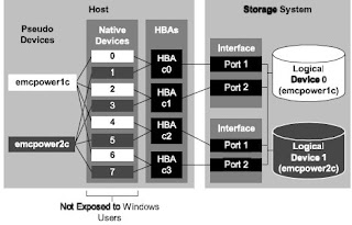
EMC PowerPath features a driver residing on the host above HBA Device Layer. This transparent componenet allows PowerPath to create Virtual(power) devices that provide failure resistant and load balanced paths to storage systems. An application needs only to reference a virt ual device while Powerpath manages path allocation to storage system.
With PowerPath, the route between server and storage system can assume a complex path. One powerpath device include as many as 32 physical I/O paths ( 16 for Clariion), with each path designated to the operating system by different name.
In most cases, the application must be reconfigured to use pseudo devices, otherwise PowerPath load balancing and path failover functionality will not be available.


The following describe whether application need to be reconfigure to use pseudo devices.
1) Windows Plateform :- No. ( Application not require to reconfigured to use Pseudo Devices )
2) AIX :- NO- For LVM, Yes, if applicaiton do not use LVM
3) HP-UX - NO
4) Solaris :- Yes, Incluing filesystem mounting tables and volume managers.
5) Linux :- Same as Solaris
if you attach new LUN to Host, powerpath automatically detect that LUN if you have exposed correctly and create device name like emcpower1c, emcpower2c etc, even when you type command on CLI like
#powermt display dev=all;
you will be able to device entry like emcpowerN.....
Hope this will help you to understand why powerpath uses pseudo devices?

What are the differences between failover modes on a CLARiiON array?

A CLARiiON array is an Active/Passive device and uses a LUN ownership model. In other words, when a LUN is bound it has a default owner, either SP-A or SP-B. I/O requests traveling to a port SP-A can only reach LUNs owned by SP-A and I/O requests traveling to a port on SP-B can only reach LUNs owned SP-B. It is necessary to have different failover methods because in certain situations a host will need to access a LUN on the non-owning SP.

The following failover modes apply:

Failover Mode 0

LUN Based Trespass Mode This failover mode is the default and works in conjunction with the Auto-trespass feature. Auto-trespass is a mode of operation that is set on a LUN by LUN basis. If Auto-Trespass is enabled on the LUN, the non-owning SP will report that the LUN exists and is available for access. The LUN will trespass to the SP where the I/O request is sent. Every time the LUN is trespassed a Unit Attention message is recorded. If Auto-trespass is disabled, the non-owning SP will report that the LUN exists but it is not available for access. If an I/O request is sent to the non-owning SP, it is rejected and the LUN’s ownership will not change.
Note: The combination of Failover Mode 0 and Auto-Trespass can be dangerous if the host is sending I/O requests to both SP-A and SP-B because the LUN will need to trespass to fulfill each request. This combination is most commonly seen on an HP-UX server using PV-Links. The Auto-trespass feature is enabled through the Initiator Type setting of HP-AutoTrespass. A host with no failover software should use the combination of Failover Mode 0 and Auto-trespass disabled.

Failover Mode 1 – Passive Not Ready Mode In this mode of operation the non-owning SP will report that all non-owned LUNs exist and are available for access. Any I/O request that is made to the non-owning SP will be rejected. A Test Unit Ready (TUR) command sent to the non-owning SP will return with a status of device not ready. This mode is similar to Failover Mode 0 with Auto-Trespass disabled. Note: This mode is most commonly used with PowerPath. To a host without PowerPath, and configured with Failover Mode 1, every passive path zoned, for example, a path to SP-B for a LUN owned by SP-A, will show to the server as Not Ready. This will show as with offline errors on a Solaris server, SC_DISK_ERR2 errors with sense bytes 0102, 0700, and 0403 on an AIX server or buffer to I/O errors on a Linux server. If PowerPath is installed, these types of messages should not occur.

Failover Mode 2 – DMP Mode In this mode of operation the non-owning SP will report that all non-owned LUNs exist and are available for access. This is similar to Failover Mode 0 with Auto-trespass Enabled. Any I/O requests made to the non-owning SP will cause the LUN to be trespassed to the SP that is receiving the request. The difference between this mode and Auto-trespass mode is that Unit Attention messages are suppressed. Note: This mode is used for some Veritas DMP configurations on some operating systems. Because of the similarities to Auto-Trespass, this mode has been known to cause “Trespass Storms.” If a server runs a script that probes all paths to the Clariion, for instance format on a Solaris server, the LUN will trespass to the non owning SP when the I/O request is sent there. If this occurs for multiple LUNs, a significant amount of trespassing will occur.

Failover Mode 3 – Passive Always Ready Mode In this mode of operation the non-owning SP will report that all non-owned LUNs exist and are available for access. Any I/O requests sent to the Non-owning SP will be rejected. This is similar to Failover Mode 1. However, any Test Unit Ready command sent from the server will return with a success message, even to the non-owning SP. Note: This mode is only used on AIX servers under very specific configuration parameters and has been developed to better handle a CLARiiON non-disruptive upgrade (NDU) when AIX servers are attached.

DMP With CLARiiON:-

CLARiiON arrays are active-passive devices that allow only one path at a time to be used for I/O. The path that is used for I/O is called the active or primary path. An alternate path (or secondary path) is configured for use in the event that the primary path fails. If the primary path to the array is lost, DMP automatically routes I/O over the secondary path or other available primary paths.

For active/passive disk arrays, VxVM uses the available primary path as long as it is accessible. DMP shifts I/O to the secondary path only when the primary path fails. This is called "failover" or "standby" mode of operation for I/O. To avoid the continuous transfer of ownership of LUNs from one controller to another, which results in a severe slowdown of I/O, do not access any LUN on other than the primary path (which could be any of four available paths on a FC4700 and CX-Series arrays).

Note: DMP does not perform load balancing across paths for active-passive disk arrays.

DMP failover functionality is supported and should attempt to limit any scripts or processes from using the passive paths to the CLARiiON array. This will prevent DMP from causing unwanted LUN trespasses.

To view potential trespasses, look at the ktrace (kt_std) information from SPcollect, messages similar the following can be seen happening with regularity.

09:07:31.995 412 820f6440 LUSM Enter LU 34 state=LU_SHUTDOWN_TRESPASS
09:07:35.970 203 820f6440 LUSM Enter LU 79 state=LU_SHUTDOWN_TRESPASS
09:07:40.028 297 820f6440 LUSM Enter LU 13 state=LU_SHUTDOWN_TRESPASS
09:07:42.840 7 820f6440 LUSM Enter LU 57 state=LU_SHUTDOWN_TRESPASS

The "Enter LU ##" is the decimal array LUN number one would see in the Navisphere Manager browser. When the messages occur, there will be no 606 trespass messages in the SP event logs. This is an indication that thetrespasses are the 'masked out' DMP trespass messages. Executing I/Os to the /dev/dsk device entry will cause this to happen.

Using the SPcollect SP_navi_getall.txt file, check the storagegroup listing to find out which hosts these LUNs belong to. Then obtain an EMCGrab/EMCReport from the affected hosts and you will need to look for a host-based process that could potentially be sending I/O down the 'passive' path. Those I/Os can be caused by performance scripts, format or devfsadm commands being run or even host monitoring software that polls all device paths.
One workaround is to install and configure EMC PowerPath. PowerPath disables the auto trespass mode and is designed to handle I/O requests properly so that the passive path is not used unless required. This will require changing the host registration parameter "failover mode" to a '1'. This failover mode is termed an "explicit mode" and it will resolve the type of trespass issues noted above.

Setting Failover Values for Initiators Connected to a Specific Storage System:

Navisphere Manager lets you edit or add storage system failover values for any or all of the HBA initiators that are connected to a storage system and displayed in the Connectivity Status dialog box for that storage system.

1. In the Enterprise Storage dialog box, navigate to the icon for the storage system whose failover properties you want to add or edit.
2. Right-click the storage system icon, and click Connectivity Status.
3. In the Connectivity Status dialog box, click Group Edit to open the Group Edit Initiators dialog box.
4. Select the initiators whose New Initiator Information values you want to add or change, and then add or edit the values in Initiator Type, ArrayCommPath and Failover Mode.
5. Click OK to save the settings and close the dialog box.
Navisphere updates the initiator records for the selected initiators, and registers any unregistered initiators.

Background Verify and Trespassing

Background Verify must be run by the SP that currently owns the LUN. Trespassing is a means of transferring current ownership of a LUN from one SP to the other. Therefore, aborting a Background Verify is part of the trespass operation – it is a necessary step.

About Me

My photo
Sr. Solutions Architect; Expertise: - Cloud Design & Architect - Data Center Consolidation - DC/Storage Virtualization - Technology Refresh - Data Migration - SAN Refresh - Data Center Architecture More info:- diwakar@emcstorageinfo.com
Blog Disclaimer: “The opinions expressed here are my personal opinions. Content published here is not read or approved in advance by EMC and does not necessarily reflect the views and opinions of EMC.”
EMC Storage Product Knowledge Sharing