means that the Clariion will write 128 blocks of data to one physical disk in the RAID Group before moving to the next disk in the RAID Group and write another 128 blocks to that disk, so on and so on.
Tier "0" is not new in storage market but for implementation purposes it has been difficult to accommodate because it requires best performance and lowest latency. Enterprise Flash disks (Solid State Disks) capable to meet this requirement. It is possible to get more performance for company most critical applications. The performance can be gained through using Flash drives supported in VMAX and DMX-4 systems. Read More →

EMC has traditionally protected failing drives using Dynamic Spares. A Dynamic Spare will take a copy of the data from a failing drive and act as a temporary mirror of the data until the drive can be replaced. The data will then be copied back to the new drive at which point the Dynamic Spare will return the spare drive pool. Two copy processes are required one to copy data to the Dynamic Spare and one to copy data back to the new drive. The copy process may impact performance and, since the Dynamic Spare takes a mirror position, can affect other dynamic devices such as BCVs.
Permanent Sparing overcomes many of these limitations by copying the data only once to a drive which has replaced the failing drive taking its original mirror position. Since the Permanent Spare
does not take an additional mirror position it will not affect Timfinder Mirror operations.
Permanent Sparing in some instances uses Dynamic Sparing as an interim step. This will be described together with the requirements for Permanent Sparing.
- Permanent Sparing is supported on all flavours of DMX.
- A Permanent Spare replaces the original failing drive and will take its original mirror position.
- Required sufficient drives of the same type as the failing drives to be installed and configured as Spares.
- Needs to enabled in the binfile (can be done via Symcli).
- Permanent Sparing will alter the back end bin and cannot be initiated when there is a Configuration Lock on the box.
- When enabled reduces the need for a CE to attend site for drive changes since drives can be replaced in batches.
- Permanent Spare will follow all configuration rules to ensure both performance and redundancy.
- Enginuity Code level must support the feature.
The following Ten Rules provided by Brocade for zoning:
Rule 1: Type of Zoning (Hard, Soft, Hardware Enforced, Soft Porting) – If security is a
priority, then a Hard Zone-based architecture coupled with Hardware Enforcement is
recommended
Rule 2: Use of Aliases – Aliases are optional with zoning. Using aliases should force some
structure when defining your zones. Aliases will also aid future administrators of the zoned
fabric. Structure is the word that comes to mind here.
Rule 3: Does the site need an extra level of security that Secure Fabric OS provides? – Add
Secure Fabric OS into the Zone Architecture if extra security is required.
Rule 4: From where will the fabric be managed? – If a SilkWorm 12000 is part of the fabric,
then the user should use it to administer zoning within the Fabric
Rule 5: Interoperability Fabric – If the fabric includes a SilkWorm 12000 and the user needs to
support a third-party switch product, then he will only be able to do WWN zoning, no
QuickLoop etc.
Rule 6: Is the fabric going to have QLFA or QL in it? – If the user is running Brocade Fabric OS
v4.0, then there are a couple things to consider before creating and setting up QLFA zones:
• QuickLoop Zoning
QL/QL zones cannot run on switches running Brocade Fabric OS v4.0. Brocade Fabric
OS v4.0 can still manage (create, remove, update) QL zones on any non-v4.0 switch.
• QuickLoop Fabric Assist
Brocade Fabric OS v4.0 cannot have a Fabric Assist host directly connected to it.
However, Brocade Fabric OS v4.0 can still be part of a Fabric Assist zone if a Fabric
Assist host is connected to a non-v4.0 switch.
Rule 7: Testing a (new) zone configuration. – Before implementing a zone the user should run
the Zone Analyzer and isolate any possible problems. This is especially useful, as fabrics
increase in size.
Rule 8: Prep work needed before enabling/changing a zone configuration. – Before enabling or
changing a fabric configuration, the user should verify that no one is issuing I/O in the zone that will change. This can have a serious impact within the fabric like databases breaking, node
panics etc. This goes the same for disk(s) that are mounted. If the user changes a zone, and a
node is mounting the storage in question, it may “vanish” due to the zone change. This may
cause nodes to panic, applications to break etc. Changes to the zone should be done during
preventative maintenance. Most sites have an allocated time each day to perform maintenance
work.
Rule 9: Potential post work requirements after enabling/changing a zone configuration. – After
changing or enabling a zone configuration, the user should confirm that nodes and storage are
able to see and access one another. Depending on the platform, the user may need to reboot one
or more nodes in the fabric with the new changes to the zone.
Rule 10: LUN masking in general. – LUN Masking should be used in conjunction with fabric
zoning for maximum effectiveness.
Conceptually, even operationally, SRDF is very similar to Timefinder. About the only difference is that SRDF works across Symms; while Timefinder works internally to one Symm.That difference, intersymm vs intrasym, means that SRDF operations can cover quite a bit of ground geographically. With the advent of geographically separated symms, the integrity of the data from one symm to the other becomes a concern. EMC has a number of operational modes in which the SRDF operates. The choice between these operational modes is a balancing act between how quickly the calling application gets an acknowledgement back versus how sure you need to be that the data has been received on the remote symm.Synchronous mode
Synchronous mode basically means that the remote symm must have the I/O in cache before the calling application receives the acknowledgement. Depending on distance between symms, this may have a significant impact on performance which is the main reason that EMC suggests this set up in a campus (damn near colocated) environment only.
If you're particularly paranoid about ensuring data on one symm is on the other, you can enable theDomino effect (I think you're supposed to be hearing suspense music in the background right about now...). Basically, the
domino effect ensures that the R1 devices will become "not ready" if the R2 devices can't be reached for any reason - effectively shutting down the filesystem(s) untilthe problem can be resolved.Semi-synchronous mode
In semi-synchronous mode, the R2 devices are one (or less) write I/O out of sync with their R1 device counterparts. The application gets the acknowledgement as soon as the first write I/O gets to the local cache. The second I/O isn't acknowledged until the first is in the remote cache. This should speed up the application over the synchronous mode. It does, however, mean that your data might be a bit out of sync with the local symm.
Adaptive Copy-Write Pending
This mode copies data over to the R2 volumes as quickly as it can; however, doesn't delay the acknowledgement to the application. This mode is useful where some data loss is permissable andlocal performance is paramount.
There's a configurable skew parameter that lists the maximum allowable dirty tracks. Once that number of pending I/Os is reached, the system switches to the predetermined mode (probably semi-synchronous) until the remote symm catches up. At that point, it switches back to adaptive copy-write pending mode.
EMC announce
A Symmetrix DMX-4 with Flash drives can deliver single-millisecond application response times and up to 30 times more IOPS than traditional 15,000 rpm Fibre Channel disk drives. Additionally, because there are no mechanical components, Flash drives require up to 98 percent less energy per IOPS than traditional disk drives. Database acceleration is one example for Flash drive performance impact. Flash drive storage can be used to accelerate online transaction processing (OLTP), accelerating performance with large indices and frequently accessed database tables. Examples of OLTP applications include Oracle and DB2 databases, and SAP R/3. Flash drives can also improve performance in batch processing and shorten batch processing windows.
Flash drive performance will help any application that needs the lowest latency possible. Examples include
· Algorithmic trading
· Currency exchange and arbitrage
· Trade optimization
· Realtime data/feed processing
· Contextual web advertising
· Other realtime transaction systems
· Data modeling
Flash drives are most beneficial with random read misses (RRM). If the RRM percentage is low, Flash drives may show less benefit since writes and sequential reads/writes already leverage Symmetrix cache to achieve the lowest possible response times. The local EMC SPEED Guru can do a performance analysis of the current workload to determine how the customer may benefit from Flash drives. Write response times of long distance SRDF/S replication could be high relative to response times from Flash drives. Flash drives cannot help with reducing response time due to long distance replication. However, read misses still enjoy low response times.
Flash drives can be used as clone source and target volumes. Flash drives can be used as SNAP source volumes. Virtual LUN Migration supports migrating volumes to and from Flash drives. Flash drives can be used with SRDF/s and SRDF/A. Metavolumes can be configured on Flash drives as long as all of the logicals in the metagroup are on Flash drives.
Limitations and Restrictions of Flash drives:
Due to the new nature of the technology, not all Symmetrix functions are currently supported on Flash drives. The following is a list of the current limitations and restrictions of Flash drives.
• Delta Set Extension and SNAP pools cannot be configured on Flash drives.
• RAID 1 and RAID 6 protection, as well as unprotected volumes, are currently not supported with Flash drives.
• TimeFinder/Mirror is currently not supported with Flash drives.
• iSeries volumes currently cannot be configured on Flash drives.
• Open Replicator of volumes configured on Flash drives is not currently supported.
• Secure Erase of Flash drives is not currently supported.
• Compatible Flash for z/OS and Compatible Native Flash for z/OS are not currently supported.
• TPF is not currently supported.
volume management .It lets organizations reduce downtime while increasing data availability, and utilize storage assets efficiently, effectively, and economically.Single-initiator zoning rule :--Each HBA port must be in a separate zone that contains it and the SP ports with which it communicates. EMC recommends single-initiator zoning as a best practice.
Fibre Channel fan-in rule:--A server can be zoned to a maximum of 4 storage systems.
Fibre Channel fan-out rule:-The Navisphere software license determines the number of servers you can connect to a CX3-10c, CX3-20c,CX3-20f, CX3-40c, CX3-40f, or CX3-80 storage systems. The maximum number of connections between servers and a storage system is defined by the number of initiators supported per storage-system SP. An initiator is an HBA
port in a that can access a storage system. Note that some HBAs have multiple ports. Each HBA port that is zoned to an SP port is one path to that SP and the storage system containing that SP. Depending on the type of storage system and the connections between its SPs and the switches, an HBA port can be zoned through different switch ports to the same SP port or to different SP ports, resulting in multiple paths between the HBA port and an SP and/or the storage system. Note that the failover software running on the server may limit the number of paths supported from the server to a single storage-system SP and from a server to the storage system.
Storage systems with Fibre Channel data ports :- CX3-10c (SP ports 2 and 3), CX3-20c (SP ports 4 and 5), CX3-20f (all ports), CX3-40c (SP ports 4 and 5), CX3-40f (all ports), CX3-80 (all ports).
Number of servers and storage systems As many as the available switch ports, provided each server follows the fan-in rule above and each storage system follows the fan-out rule above, using WWPN switch zoning.
Fibre connectivity
Fibre Channel Switched Fabric (FC-SW) connection to all server types.
Fibre Channel switch terminologySupported Fibre Channel switches.
Fabric - One or more switches connected by E_Ports. E_Ports are switch ports that are used only for connecting switches together.
ISL - (Inter Switch Link). A link that connects two E_Ports on two different switches.
Path - A path is a connection between an initiator (such as an HBA port) and a target (such as an SP port in a storage system). Each HBA port that is zoned to a port on an SP is one path to that SP and the storage system containing that SP. Depending on the type of storage system and the connections between its SPs and the switch fabric, an HBA port can be zoned through different switch ports to the same SP port or to different SP ports, resulting in multiple paths between the HBA port and an SP and/or the storage system. Note that the failover software running on the server may limit the number of paths supported from the server to a single storage-system
SP and from a server to the storage system.
The global reserved LUN pool works with replication software, such as SnapView, SAN Copy, and MirrorView/A to store data or information required to complete a replication task. The reserved LUN pool consists of one or more private LUNs. The LUN becomes private when you add it to the reserved LUN pool. Since the LUNs in the reserved LUN pool are private LUNs, they cannot belong to storage groups and a server cannot perform I/O to them.
Before starting a replication task, the reserved LUN pool must contain at least one LUN for each source LUN that will participate in the task. You can add any available LUNs to the reserved LUN pool. Each storage system manages its own LUN pool space and assigns a separate reserved LUN (or multiple LUNs) to each source LUN.
All replication software that uses the reserved LUN pool shares the resources of the reserved LUN pool. For example, if you are running an incremental SAN Copy session on a LUN and a snapshot session on another LUN, the reserved LUN pool must contain at least two LUNs - one for each source LUN. If both sessions are running on the same source LUN, the sessions will share a reserved LUN.
Estimating a suitable reserved LUN pool size
Each reserved LUN can vary in size. However, using the same size for each LUN in the pool is easier to manage because the LUNs are assigned without regard to size; that is, the first available free LUN in the global reserved LUN pool is assigned. Since you cannot control which reserved LUNs are being used for a particular replication session, EMC recommends that you use a standard size for all reserved LUNs. The size of these LUNs are dependent on If you want to optimize space utilization, the recommendation would be to create many small reserved LUNs, which allows for sessions requiring minimal reserved LUN space to use one or a few reserved LUNs, and sessions requiring more reserved LUN space to use multiple reserved LUNs. On the other hand, if you want to optimize the total number of source LUNs, the recommendation would be to create many large reserved LUNs, so that even those sessions which require more reserved LUN space only consume a single reserved LUN.
The following considerations should assist in estimating a suitable reserved LUN pool size for the storage system.
If you wish to optimize space utilization , use the size of the smallest source LUN as the basis of your calculations. If you wish to optimize the total number of source LUNs , use the size of the largest source LUN as the basis of your calculations. If you have a standard online transaction processing configuration (OLTP), use reserved LUNs sized at 10-20%. This tends to be an appropriate size to accommodate the copy-on-first-write activity.
If you plan on if you plan on creating multiple sessions per source LUN, anticipate a large number of writes to the source LUN, or anticipate a long duration time for the session, you may also need to allocate additional reserved LUNs. With any of these cases, you should increase the calculation accordingly. For instance, if you plan to have 4 concurrent sessions running for a given source LUN, you might want to increase the estimated size by 4 – raising the typical size to 40-80%.
Lets talk about SRDF feature in DMX for disaster recovery/remote replication/data migration. In today’s business environment it is imperative to have the necessary equipment and processes in place to meet stringent service-level requirements. Downtime is no longer an option. This means you may need to remotely replicate your business data to ensure availability. Remote data replication is the most challenging of all disaster recovery activities. Without the right solution it can be complex, error prone, labor intensive, and time consuming.
SDRF/S addresses these problems by maintaining real-time data mirrors of specified Symmetrix logical volumes. The implementation is a remote mirror, Symmetrix to Symmetrix.
¨ The most flexible synchronous solution in the industry
¨ Cost effective solution with native GigE connectivity
¨ Proven reliability
¨ Simultaneous operation with SRDF/A, SRDF/DM and/or SRDF/AR in the same system
¨ Dynamic, Non-disruptive mode change between SRDF/S and SRDF/A
¨ Concurrent SRDF/S and SRDF/A operations from the same source device
¨ A powerful component of SRDF/Star, multi-site continuous replication over distance with zero RPO service levels.
¨ Business resumption is now a matter of a systems restart. No transportation, restoration, or restoring from tape is required. And SRDF/S supports any environment that connects to a Symmetrix system – mainframe, open system, NT, AS4000, or Celerra.
¨ ESCON fiber, fiber channel, Gigabit Ethernet, T3, ATM, I/P, and Sonet rings are supported, providing choice and flexibility to meet specific service level requirements. SRDF/S can provide real-time disk mirrors across long distances without application performance degradation, along with reduced communication costs. System consistency is provided by ensuring that all related data volumes are handled identically – a feature unique to EMC. Hope this litte article will help you to understand about SRDF/S.
TimeFinder/Clone creates full-volume copies of production data, allowing you to run simultaneous tasks in parallel on Symmetrix systems. In addition to real-time, nondisruptive backup and restore, TimeFinder/Clone is used to compress the cycle time for such processes as application testing, software development, and loading or updating a data warehouse. This significantly increases efficiency and productivity while maintaining continuous support for the production needs of the enterprise.
¨ Ability to protect Clone BCVs with RAID-5
¨ Create instant Mainframe SNAPs of datasets or logical volumes for OS/390 data, compatible with STK SNAPSHOT for RVA.
¨ Facilitate more rapid testing of new versions of operating systems, data base managers, file systems etc., as well as new applications Load or update data warehouses as needed
¨ Allow pro-active database validation, thus minimizing exposure to faulty applications.
¨ Allows multiple copies to be retained at different checkpoints for lowered RPO and RTO, thus improving service levels.
¨ Can be applied to data volumes across multiple Symmetrix devices using EMC’s unique consistency technology (TimeFinder/Consistency Group option required).
AX150 :-Dual storage processor enclosure with Fibre-Channel interface to host and SATA-2 disks. AX150i :-Dual storage processor enclosure with iSCSI interface to host and SATA-2 disks. AX100 :- Dual storage processor enclosure with Fibre-Channel interface to host and SATA-1 disks.
AX100SC
Single storage processor enclosure with Fibre-Channel interface to host and SATA-1 disks.
AX100i
Dual storage processor enclosure with iSCSI interface to host and SATA-1 disks.
AX100SCi
Single storage processor enclosure with iSCSI interface to host and SATA-1 disks.
CX3-80
SPE2 - Dual storage processor (SP) enclosure with four Fibre-Channel front-end ports and four back-end ports per SP.
CX3-40
SP3 - Dual storage processor (SP) enclosure with two Fibre Channel front-end ports and two back-end ports per SP.
CX3-40f
SP3 - Dual storage processor (SP) enclosure with four Fibre Channel front -end ports and four back-end ports per SP
CX3-40c
SP3 - Dual storage processor (SP) enclosure with four iSCSI front-end ports, two Fibre Channel front -end ports, and two back-end ports per SP.
CX3-20
SP3 - Dual storage processor (SP) enclosure with two Fibre Channel front-end ports and a single back-end port per SP.
CX3-20f
SP3 - Dual storage processor (SP) enclosure with six Fibre Channel front-end ports, and a single back-end port per SP.
CX3-20c
SP3 - Dual storage processor (SP) enclosure with four iSCSI front-end ports, two Fibre Channel front-end ports, and a single back-end port per SP.
CX600, CX700
SPE - based storage system with model CX600/CX700 SP, Fibre-Channel interface to host, and Fibre Channel disks
CX500, CX400, CX300, CX200
DPE2 - based storage system with model CX500/CX400/CX300/CX200 SP, Fibre-Channel interface to host, and Fibre Channel disks.
CX2000LC
DPE2- based storage system with one model CX200 SP, one power supply (no SPS),Fibre-Channel interface to host, and Fibre Channel disks.
C1000 Series
10-slot storage system with SCSI interface to host and SCSI disks
C1900 Series
Rugged 10-slot storage system with SCSI interface to host and SCSI disks
C2x00 Series
20-slot storage system with SCSI interface to host and SCSI disks
C3x00 Series
30-slot storage system with SCSI or Fibre Channel interface to host and SCSI disks
FC50xx Series
DAE with Fibre Channel interface to host and Fibre Channel disks
FC5000 Series
JBOD with Fibre Channel interface to host and Fibre Channel disks
FC5200/5300 Series
iDAE -based storage system with model 5200 SP, Fibre Channel interface to host, and Fibre channel disks
FC5400/5500 Series
DPE -based storage system with model 5400 SP, Fibre Channel interface to host, and Fibre channel disks
FC5600/5700 Series
DPE -based storage system with model 5600 SP, Fibre Channel interface to host, and Fibre Channel disks
FC4300/4500 Series
DPE -based storage system with either model 4300 SP or model 4500 SP, Fibre Channel interface to host, and Fibre Channel disks
FC4700 Series
DPE -based storage system with model 4700 SP, Fibre Channel interface to host, and Fibre Channel disks
IP4700 Series
Rackmount Network-Attached storage system with 4 Fibre Channel host ports and Fibre Channel disks.
RAID 6 Protection
the assigned interface card.We have discussed regarding Symmetric DMX-3. Lets talk about Symmetrix Device. DMX-3 system applies a high degree of virtualization between what host sees and the actual disk drives. This device has logical volume address that the host can address. Let me clear that “A symmetrix Device is not a physical disk.” Before actually hosts see the symmetrix device, you need to define path means mapping the devices to Front-end director and then you need to set FA-PORT attribute for specific Host. Let not discuss configuration details now. I am trying to explain what Symmetrix device is if this is not physical disk and how it will be created.
You can create up to four mirrors for each Symmetrix device. The Mirror positions are designed M1, M2, M3 and M4. When we create a device and specify its configuration type, the Symmetrix system maps the device to one or more complete disks or part of disks known as Hyper Volumes/Hypers. As a rule, a device maps to at least two mirror means hypers on two different disks, to maintain multiple copies of data.
Most of user asked me what are basic differences between EMC Clone/Mirror/Snapshot? This is really confusing terminology because most of things will be same logically.Only thing change that is implementation and purpose of uses. I am trying to write basic and common differences:
1) A clone is a full copy of data in a source LUN. A snapshot is a point-in time "virtual" copy that does not occupy any disk space.
2) A snapshot can be created or destroyed in seconds, unlike a clone or mirror. A clone, for example, can take minutes to hours to create depending on the size of the source LUN.
3) A clone or mirror requires exactly the same amount of disk space as the source LUN. A snapshot cache LUN generally requires approximately 10% to 20% of the source LUN size.
4) A clone is an excellent on-array solution that enables you to recover from a data corruption issue. Mirrors are designed for off-site data recovery.
5) A clone is typically fractured after it is synchronized while a mirror is not fractured but instead is actively and continuously being synchronized to any changes on the source LUN.
Clones and mirrors are inaccessible to the host until they are fractured. Clones can be easily resynchronized in either direction. This capability is not easily implemented with mirrors.
Restoring data after a source LUN failure is instantaneous using clones after a reverse synchronization is initialized. Restore time from a snapshot depends on the time it takes to restore from the network or from a backup tape.
Once a clone is fractured, there is no performance impact (that is, performance is comparable to the performance experienced with a conventional LUN). For snapshots, the performance impact is above average and constant due to copy on first write (COFW).
I left one more term EMC BCV(Business Continuity Volume). It is totally different concept thought. I will try to cover in upcoming post though I have discussed about EMC BCV in my older post. But it is more or less cloning only only implementation change.
As we know that we have different type of RAID but all the raid type are not suitable for the all application. We select raid type depending on the application and IO load/Usages. Actually there are so many factor involved before you select suitable raid type for any application. I am trying to give brief idea in order to select best raid type for any application. You can select raid type depending on your environment.
When to Use RAID 5
RAID 5 is favored for messaging, data mining, medium-performance media serving, and RDBMS implementations in which the DBA is effectively using read-ahead and write-behind. If the host OS and HBA are capable of greater than 64 KB transfers, RAID 5 is a compelling choice.
These application types are ideal for RAID 5:
1) Random workloads with modest IOPS-per-gigabyte requirements
2) High performance random I/O where writes represent 30 percent or less of the workload
3) A DSS database in which access is sequential (performing statistical analysis on sales records)
4) Any RDBMS table space where record size is larger than 64 KB and access is random (personnel records with binary content, such as photographs)
5) RDBMS log activity
6) Messaging applications
7) Video/Media
When to Use RAID 1/0
RAID 1/0 can outperform RAID 5 in workloads that use very small, random, and write-intensive I/O—where more than 30 percent of the workload is random writes. Some examples of random, small I/O workloads are:
1) High-transaction-rate OLTP
2) Large messaging installations
3) Real-time data/brokerage records
4) RDBMS data tables containing small records that are updated frequently (account balances)
5) If random write performance is the paramount concern, RAID 1/0 should be used for these applications.
When to Use RAID 3
RAID 3 is a specialty solution. Only five-disk and nine-disk RAID group sizes are valid for CLARiiON RAID 3. The target profile for RAID 3 is large and/or sequential access.
Since Release 13, RAID 3 LUNs can use write cache. The restrictions previously made for RAID 3—single writer, perfect alignment with the RAID stripe—are no longer necessary, as the write cache will align the data. RAID 3 is now more effective with multiple writing streams, smaller I/O sizes (such as 64 KB) and misaligned data.
RAID 3 is particularly effective with ATA drives, bringing their bandwidth performance up to Fibre Channel levels.
When to Use RAID 1
With the advent of 1+1 RAID 1/0 sets in Release 16, there is no good reason to use RAID 1. RAID 1/0 1+1 sets are expandable, whereas RAID 1 sets are not.
stop and start the Navisphere Agent. For example:I have been posting article related to CLARiiON recently. Lets talk about DMX Series. It is the most popular storage array from EMC. To manage DMX we have tool called ECC ( EMC Control Center, SMC and SYMCLI). Let me first explain what is gatekeeper and what is use?
To perform software operations on the Symmetrix, we use the low level SCSI command. To send SCSI commands to the Symmetrix, we need to open a device. We refer to the device we open as a gatekeeper. Symmetrix gatekeepers provide communication paths into the Symmetrix for external software monitoring and/or controlling the Symmetrix. There is nothing special about a gatekeeper, any host visible device can be used for this purpose. We do not actually write any data on this device, nor do we read any date from this device. It is simply a SCSI target for our special low level SCSI commands. We do perform I/O to these devices and this can interfere with applications using the same device. This is why we always configure small devices (NO data is actually stored) and map them to hosts to be used as "gatekeepers". Solutions Enabler will consider any device with 10 cylinders or less to be the preferred gatekeeper device.
Now you must have understood what is gatekeeper devices. Let me explain more about uses like how many gatekeeper you want to present host so there will be no performance impact.
A general recommendation for the number of gatekeepers for a single host with few applications running is 8. However, a common rule of thumb is a minimum of 6. For a host on which many applications running, 16 is recommended. A gatekeeper should not be mapped/masked to more than one host.
Granular Recommendation (for Solutions Enabler) :
It is hard to recommend an exact number of gatekeepers required for a single host. The number of gatekeeper's required depends on the specific host's configuration and role. This is because it directly relates to performance, therefore it is a subjective number. The following is a recommendation based upon a number of variables pertaining to that specific host. At least 2 gatekeepers for simple Solutions Enabler commands and 1 additional gatekeeper for each daemon or EMC Control Center Agent running on the host.
Granular Recommendation (for Control Center) :
• Two gatekeepers are required when the Storage Agent for Symmetrix is installed on the host, and two (total of four) additional gatekeepers are required when you use Symmetrix Configure commands to manage the Symmetrix system. Each Symmetrix system needs only two Symmetrix agents. The agents need to be installed on separate hosts. This is to provide for
failover when the primary agent goes down for maintenance (or failure).
• Common Mapping Agent and host agents do not require a gatekeeper.
• Note: SYMCLI scripts should not use gatekeepers assigned to ControlCenter; they should have their own.
Gatekeepers are typically 6 cylinders or 2888 KB in Size. All gatekeeper type devices should be protected by either RAID-1 or RAID-S.
Hope this will help you in deciding number of gatekeeper to assign the host.Because it is matter of performance.
If you have a multihomed host and are running like :
· IBM AIX,
· HP-UX,
· Linux,
· Solaris,
· VMware ESX Server (2.5.0 or later), or
· Microsoft Windows
you must create a parameter file for Navisphere Agent, named agentID.txt
About the agentID.txt file:
or edit a file named agentID.txt in either / (root) or in a directory of your choice.We have discussed about CLARiiON. How to create LUN,RAID Group etc. before I shold discuss about adding storage to host. I must discuss about Navisphere Host agent. This is most important service/daemon which runs on host and communicate with CLARiiON. Without Host agent you can not resgister host with storage group automatically. Then if you want register host with Navishere Host agent then you need to register manually.
You can change the storage system password in Navisphere Manager as follows:
1. Open Navisphere Manager
2. Click Tools > Security > Change Password.
3. In the Change Password window, enter the old (current) password in the Old Password text box.
4. Enter the new password in the New Password text box and then enter it again in the Confirm New Password text box.
5. Click OK to apply the new password or Cancel to keep the current password.
6. In the confirmation popup, click either Yes to change the password or No to cancel the change and retain your current (old) password.
Note: If you click Yes, you will briefly see "The operation successfully completed" and then you will be disconnected. You will need to log back in using the new password.
I have discussed about lab exercise for Storage Administration purpose, Now, Lets talk about something technical. You understand that we can create Raid 5 protected LUN means we will use striping. So, How will you calculate stripe size of LUN.
Before calculating the stripe size of data in Clariion , we have discussed about how many disks make up the Raid Group, as well as the Raid Type.
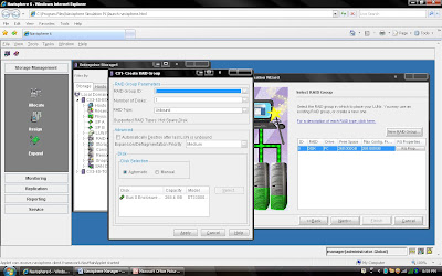
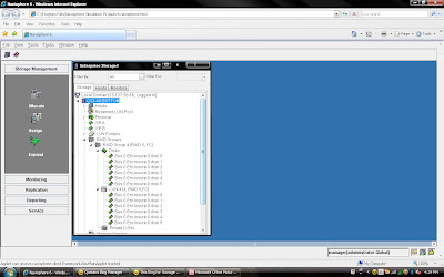
that of the five disks that make up the Raid Group, four of the disks are used to store the data, and the remaining disk is used to store the parity information for the stripe of data in the event of a disk failure and rebuild. In Clariion settings of a disk format in which it formats the disk into 128 blocks for the Element Size (amount of blocks written to a disk before writing/striping to the next disk in the Raid Group), which is equal to the 64 KB Chunk Size of data that is written to a disk before writing/striping to the next disk in the Raid Group. To determine the Data Stripe Size, we simply calculate the number of disks in the Raid Group for Data (4) x the amount of data written per disk (64 KB), and get the amount of data written in a Raid 5, Five disk Raid Group (4 + 1) as 256 KB of data. To get the Element Stripe Size, we calculate the number of disks in the Raid Group (4) x the number of blocks written per disk (128 blocks) and get the Element Stripe Size of 512 blocks.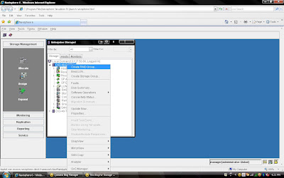 2) Once you have selected create group, it will pop up raid group creation wizard. Here you have to select so many option depending on your requirement. First select RAID Group ID. This is unique id. Then select how many disk. what it means? Let discuss for example you want to create RAID 5(3+1) then you should select 4 disk. Means there will be 4 spindle
 and striping will be done on 3 disk and one will be for parity. If you want to create more spindle for performance then select more disk with raid 5 configuration like you can select 8 disk for raid 5 (7+1).Here you have option to allocate direct disk as well. then you can select disk only. Now, you have understood how to select number of disk. Next things select raid protection level.
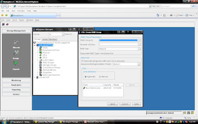 Rest, you can select default. but suppose you want to create raid group on particular disk because in same CX Frame you can have different type of disk then you can select manual then select particular disk. under disk selection tab.
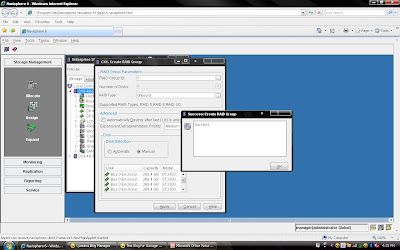
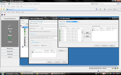 Once you have selected the all the value you can click apply. It will create RAID Group with given configuration. It will pop up message that RAID Group Created Successfully.If you want to create more group you can create using wizard otherwise click cancel.
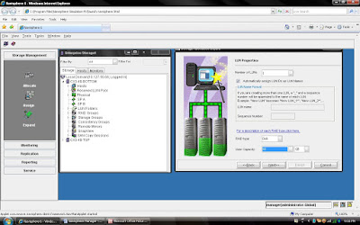
 Once you have created Raid Group you can bind the lun. What is meaning of binding? Lets focus what happen when you created RAID Group. Raid Group is something like storage pool. It will create usable storage space according to number of disk you have selected and raid group type. For example we have created Raid Group 4 and it size is 1600 GB. But you want to allocate 5 LUN each LUN size would be 100 GB or any combination of size until you you exhaust the space of the raid group. So it is call binding the LUN. Means, you have taken out some space for each LUN and allocated to Host. Each LUN will have own properties but will belong to Raid Group 4. So in short when you select number of disk while creating a particular group. CLARiiON Operating System will not allow you to use same disk of some other raid protection level.
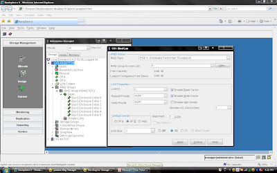
You have already created Raid 5 and have available space on them so select Raid 5 in Raid Type. Select Raid Group number which belong to Raid 5, for example we have created Raid Group 4 as Raid 5 level protection. Once you have selected Raid Group it will show the space available on this group.In our case we have 1608 GB space available on raid group 4. Now, I want to create 50 GB space out of 1608 GB. Once you have selected Raid Group Number you can select LUN number and properties. like LUN name, LUN Count means how many LUN you want to create with Same size. In most of case all will be default value. Generally select Default Owner as auto. let system will decide who suppose to own the device. In ClARiiON there is concept LUN ownership, at any time only one Storage Processor can own the LUN. I will cover LUN Ownership model later. Once you have selected you can click apply.
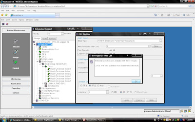 Once you have created all the LUN you can cancel that window and expand the particular raid group you can see that LUN will be listed.
EMC Brings Flash Drives in DMX-4 Frame
EMC made a important announcement with respect to its 73 GB and 146 GB flash drives or solid state drives (SSD). Flash Drives and SSD represent a new solid-state storage tier, “tier 0”, for symmetrix DMX-4. In addition to that EMC will offer Virtual Provisioning for Symmetrix 3 and 4 as well 1 TB SATA II drives.
With this announcement EMC became first storage vendor to integrate Flash Technology into its enterprise-class arrays. There as excitement in industry who is looking for faster transaction and performance. Why this much excitement for new customer? I will be discussing some technical stuff in coming paragraph.
With flash drive technology in a Symmetrix DMX-4 storage system, a credit card provider could clear up to six transactions in the time it once took to process a single transaction. Overall, EMC’s efforts could significantly alter the dynamics of the flash SSD market, where standalone flash storage systems have been available only from smaller vendors.
storage system by about 10%. But in high-end business applications where every bit of IOPS performance counts, that premium becomes entirely acceptable. When an organization truly needs a major boost then flash drives are a very real and very reasonable solution.
# Flash dives manufactured by STEC,Inc
# DMX-4 uses RAID 5(3+1) and (7+1) for flash drives
# Flash drives will operate on a 2GB/s FC loop
# Flash drives have in two size 73 GB and 146 GB 3।5” FC drive form factor at 2GB/s
# Flash drives support both format FBA and CKD emulation
# Limitation: - All the members must be Flash drives within same quadrant। (DA pair)
# Must have at least one flash drive as a Hot Spare।
# RAID 1 and RAID 6 are also in qualification
# Mixing Flash & Disk drives on the same loop is allowed
# PowerVault drives must be hard disk drives
# Maximum 32 flash drives per DA
# Cache Partiioning and QOS priority control highly recommended
# Flash Drives cab be protected with TimeFinder and SRDF
Most Suitable for Customer like:
# Currency Exchange & Arbitrage
# Trade Optimization
# Real Time Data/Feed Processing
# Credit Card Fraud Detection
# Contextual Web Advertising
# Real Time Transaction Systems
# Data Modeling & Analysis
One Flash drive can deliver IOPS equivalent to 30 15K hard disk drives with approximately 1 ms application response time. This means Flash memory achieves unprecedented performance and the lowest latency ever available in an enterprise-class storage array.
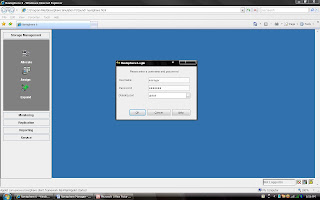
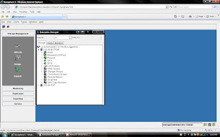
I am going to demonstrate full LAB exercise of CLARiiON. If anybody interested to any specific LAB exercise please send me mail I will try to help and give LAB exercise. There are many exercise like:
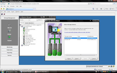
1) Create RAID Group
2) Bind the LUN
3) Create Storage Group
4) Register the Host
5) Present LUN to Host
6) Create Meta LUN etc.
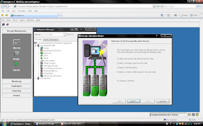
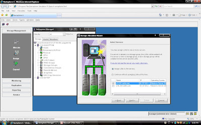
to this server or you can continue without assigning.