Showing posts with label CLARiiON. Show all posts


The Clariion Formats the disks in Blocks. Each Block written out to the disk is 520 bytes in size. Of the 520 bytes, 512 bytes is used to store the actual DATA written to the block. The remaining 8 bytes per block is used by the Clariion to store System Information, such as a Timestamp, Parity Information, Checksum Data.
Element Size – The Element Size of a disk is determined when a LUN is bound to the RAID Group. In previous versions of Navisphere, a user could configure the Element Size from 4 blocks per disk 256 blocks per disk. Now, the default Element Size in Navisphere is 128. This

means that the Clariion will write 128 blocks of data to one physical disk in the RAID Group before moving to the next disk in the RAID Group and write another 128 blocks to that disk, so on and so on.
Chunk Size – The Chunk Size is the amount of Data the Clariion writes to a physical disk at a time. The Chunk Size is calculated by multiplying the Element Size by the amount of Data per block written by the Clariion.
128 blocks x 512 bytes of Data per block = 65,536 bytes of Data per Disk. That is equal to 64 KB. So, the Chunk Size, the amount of Data the Clariion writes to a single disk, before writing to the next disk in the RAID Group is 64 KB.

Single-initiator zoning rule :--Each HBA port must be in a separate zone that contains it and the SP ports with which it communicates. EMC recommends single-initiator zoning as a best practice.
Fibre Channel fan-in rule:--A server can be zoned to a maximum of 4 storage systems.
Fibre Channel fan-out rule:-The Navisphere software license determines the number of servers you can connect to a CX3-10c, CX3-20c,CX3-20f, CX3-40c, CX3-40f, or CX3-80 storage systems. The maximum number of connections between servers and a storage system is defined by the number of initiators supported per storage-system SP. An initiator is an HBA
port in a that can access a storage system. Note that some HBAs have multiple ports. Each HBA port that is zoned to an SP port is one path to that SP and the storage system containing that SP. Depending on the type of storage system and the connections between its SPs and the switches, an HBA port can be zoned through different switch ports to the same SP port or to different SP ports, resulting in multiple paths between the HBA port and an SP and/or the storage system. Note that the failover software running on the server may limit the number of paths supported from the server to a single storage-system SP and from a server to the storage system.

Storage systems with Fibre Channel data ports :- CX3-10c (SP ports 2 and 3), CX3-20c (SP ports 4 and 5), CX3-20f (all ports), CX3-40c (SP ports 4 and 5), CX3-40f (all ports), CX3-80 (all ports).
Number of servers and storage systems As many as the available switch ports, provided each server follows the fan-in rule above and each storage system follows the fan-out rule above, using WWPN switch zoning.
Fibre connectivity
Fibre Channel Switched Fabric (FC-SW) connection to all server types.
Fibre Channel switch terminologySupported Fibre Channel switches.
Fabric - One or more switches connected by E_Ports. E_Ports are switch ports that are used only for connecting switches together.
ISL - (Inter Switch Link). A link that connects two E_Ports on two different switches.
Path - A path is a connection between an initiator (such as an HBA port) and a target (such as an SP port in a storage system). Each HBA port that is zoned to a port on an SP is one path to that SP and the storage system containing that SP. Depending on the type of storage system and the connections between its SPs and the switch fabric, an HBA port can be zoned through different switch ports to the same SP port or to different SP ports, resulting in multiple paths between the HBA port and an SP and/or the storage system. Note that the failover software running on the server may limit the number of paths supported from the server to a single storage-system
SP and from a server to the storage system.


LUN to bind Restrictions and recommendations ----------- Any LUN You can bind only unbound disk modules. All disk modules in a must have the same capacity to fully use the modules' storage space.
--- In AX-series storage systems, binding disks into LUNs is not supported.
RAID 5 - You must bind a minimum of three and no more than sixteen disk modules. We recommend you bind five modules for more efficient use of disk space. In a storage system with SCSI disks, you should use modules on different SCSI buses for highest availability. *
RAID 3 - You must bind exactly five or nine disk modules in a storage system with Fibre Channel disks and exactly five disk modules in a storage system with SCSI disks. In a storage system with SCSI disks, you should use modules on separate SCSI buses for highest availability. You cannot bind a RAID 3 LUN until you have allocated storage-system memory for the LUN, unless on a FC4700 or CX-series *
IMPORTANT: RAID 3, non FC4700/CX-series does not allow caching, when binding RAID 3 LUNS, the -c cache-flags switch do not apply
RAID 1 - You must bind exactly two disk modules. *
RAID 0 - You must bind a minimum of three and no more than sixteen disk modules. If possible in a storage system with SCSI disks, use modules on different SCSI buses for highest availability. *
RAID 1/0 - You must bind a minimum of four but no more than sixteen disk modules, and it must be an even number of modules. Navisphere Manager pairs modules into mirrored images in the order in which you select them. The first and second modules you select are a pair of mirrored images; the third and fourth modules you select are another pair of mirrored images; and so on. The first module you select in each pair is the primary image, and the second module is the secondary image. If possible in a storage system with SCSI disks the modules you select for each pair should be on different buses for highest availability. *individual disk unit none.

The global reserved LUN pool works with replication software, such as SnapView, SAN Copy, and MirrorView/A to store data or information required to complete a replication task. The reserved LUN pool consists of one or more private LUNs. The LUN becomes private when you add it to the reserved LUN pool. Since the LUNs in the reserved LUN pool are private LUNs, they cannot belong to storage groups and a server cannot perform I/O to them.

Before starting a replication task, the reserved LUN pool must contain at least one LUN for each source LUN that will participate in the task. You can add any available LUNs to the reserved LUN pool. Each storage system manages its own LUN pool space and assigns a separate reserved LUN (or multiple LUNs) to each source LUN.
All replication software that uses the reserved LUN pool shares the resources of the reserved LUN pool. For example, if you are running an incremental SAN Copy session on a LUN and a snapshot session on another LUN, the reserved LUN pool must contain at least two LUNs - one for each source LUN. If both sessions are running on the same source LUN, the sessions will share a reserved LUN.

Estimating a suitable reserved LUN pool size

Each reserved LUN can vary in size. However, using the same size for each LUN in the pool is easier to manage because the LUNs are assigned without regard to size; that is, the first available free LUN in the global reserved LUN pool is assigned. Since you cannot control which reserved LUNs are being used for a particular replication session, EMC recommends that you use a standard size for all reserved LUNs. The size of these LUNs are dependent on If you want to optimize space utilization, the recommendation would be to create many small reserved LUNs, which allows for sessions requiring minimal reserved LUN space to use one or a few reserved LUNs, and sessions requiring more reserved LUN space to use multiple reserved LUNs. On the other hand, if you want to optimize the total number of source LUNs, the recommendation would be to create many large reserved LUNs, so that even those sessions which require more reserved LUN space only consume a single reserved LUN.

The following considerations should assist in estimating a suitable reserved LUN pool size for the storage system.
If you wish to optimize space utilization , use the size of the smallest source LUN as the basis of your calculations. If you wish to optimize the total number of source LUNs , use the size of the largest source LUN as the basis of your calculations. If you have a standard online transaction processing configuration (OLTP), use reserved LUNs sized at 10-20%. This tends to be an appropriate size to accommodate the copy-on-first-write activity.
If you plan on if you plan on creating multiple sessions per source LUN, anticipate a large number of writes to the source LUN, or anticipate a long duration time for the session, you may also need to allocate additional reserved LUNs. With any of these cases, you should increase the calculation accordingly. For instance, if you plan to have 4 concurrent sessions running for a given source LUN, you might want to increase the estimated size by 4 – raising the typical size to 40-80%.

AX150 :-Dual storage processor enclosure with Fibre-Channel interface to host and SATA-2 disks. AX150i :-Dual storage processor enclosure with iSCSI interface to host and SATA-2 disks. AX100 :- Dual storage processor enclosure with Fibre-Channel interface to host and SATA-1 disks.
AX100SC
Single storage processor enclosure with Fibre-Channel interface to host and SATA-1 disks.
AX100i
Dual storage processor enclosure with iSCSI interface to host and SATA-1 disks.
AX100SCi
Single storage processor enclosure with iSCSI interface to host and SATA-1 disks.
CX3-80
SPE2 - Dual storage processor (SP) enclosure with four Fibre-Channel front-end ports and four back-end ports per SP.
CX3-40
SP3 - Dual storage processor (SP) enclosure with two Fibre Channel front-end ports and two back-end ports per SP.
CX3-40f
SP3 - Dual storage processor (SP) enclosure with four Fibre Channel front -end ports and four back-end ports per SP
CX3-40c
SP3 - Dual storage processor (SP) enclosure with four iSCSI front-end ports, two Fibre Channel front -end ports, and two back-end ports per SP.
CX3-20
SP3 - Dual storage processor (SP) enclosure with two Fibre Channel front-end ports and a single back-end port per SP.
CX3-20f
SP3 - Dual storage processor (SP) enclosure with six Fibre Channel front-end ports, and a single back-end port per SP.
CX3-20c
SP3 - Dual storage processor (SP) enclosure with four iSCSI front-end ports, two Fibre Channel front-end ports, and a single back-end port per SP.
CX600, CX700
SPE - based storage system with model CX600/CX700 SP, Fibre-Channel interface to host, and Fibre Channel disks
CX500, CX400, CX300, CX200
DPE2 - based storage system with model CX500/CX400/CX300/CX200 SP, Fibre-Channel interface to host, and Fibre Channel disks.
CX2000LC
DPE2- based storage system with one model CX200 SP, one power supply (no SPS),Fibre-Channel interface to host, and Fibre Channel disks.
C1000 Series
10-slot storage system with SCSI interface to host and SCSI disks
C1900 Series
Rugged 10-slot storage system with SCSI interface to host and SCSI disks
C2x00 Series
20-slot storage system with SCSI interface to host and SCSI disks
C3x00 Series
30-slot storage system with SCSI or Fibre Channel interface to host and SCSI disks
FC50xx Series
DAE with Fibre Channel interface to host and Fibre Channel disks
FC5000 Series
JBOD with Fibre Channel interface to host and Fibre Channel disks
FC5200/5300 Series
iDAE -based storage system with model 5200 SP, Fibre Channel interface to host, and Fibre channel disks
FC5400/5500 Series
DPE -based storage system with model 5400 SP, Fibre Channel interface to host, and Fibre channel disks
FC5600/5700 Series
DPE -based storage system with model 5600 SP, Fibre Channel interface to host, and Fibre Channel disks
FC4300/4500 Series
DPE -based storage system with either model 4300 SP or model 4500 SP, Fibre Channel interface to host, and Fibre Channel disks
FC4700 Series
DPE -based storage system with model 4700 SP, Fibre Channel interface to host, and Fibre Channel disks
IP4700 Series
Rackmount Network-Attached storage system with 4 Fibre Channel host ports and Fibre Channel disks.

We have storage array product from different vendor. Everyone talkes about active-active and active-passive device technology. With different types of storage arrays and host connection types, it is important to understand the difference between active-active and active-passive devices. Here is short explanation of the differences:
Active-active (for example, Symmetrix arrays)
In an active-active storage system, if there are multiple interfaces to a logical device, they all provide equal access to the logical device. Active-active means that all interfaces to a device are active simultaneously.
Active-passive (for example, CLARiiON arrays)
Active-passive means that only one interface to a device is active at a time, and any others are passive with respect to that device and waiting to take over if needed.
In an active-passive storage system, if there are multiple interfaces to a logical device, one of them is designated as the primary route to the device (that is, the device is assigned to that interface card). Typically, assigned devices are distributed equally among interface cards. I/O is not directed to paths connected to a non-assigned interface. Normal access to a device through any interface card other than its assigned one is either impossible (for example, on CLARiiON arrays) or possible, but much slower than access through the assigned interface card.
In the event of a failure, logical devices must be moved to another interface. If an interface card fails, logical devices are reassigned from the broken interface to another interface. This reassignment is initiated by the other, functioning interface. If all paths from a host to an interface fail, logical devices accessed on those paths are reassigned to another interface with which the host can still communicate. EitherApplication-Transparent Failover (ATF) or PowerPath, which instructs the storage system to make the reassignment, initiates this reassignment. These reassignments are known as trespassing. Trespassing can take several seconds to complete. However, I/Os do not fail during it. After devices are trespassed, ATF or PowerPath detects the changes and seamlessly routes data via the new route. After a trespass, logical devices can be trespassed back to their assigned interface. This occurs automatically if PowerPath's periodic autorestore feature is enabled. It occurs manually if powermt restore is run, which is the faster approach. Or if ATF is in use, a manual restore of the path can be executed to restore the original path.

If you have a multihomed host and are running like :
· IBM AIX,
· HP-UX,
· Linux,
· Solaris,
· VMware ESX Server (2.5.0 or later), or
· Microsoft Windows
you must create a parameter file for Navisphere Agent, named agentID.txt
About the agentID.txt file:

This file, agentID.txt (case sensitive), ensures that the Navisphere Agent binds to the correct HBA/NIC for registration and therefore registers the host with the correct storage system. The agentID.txt file must contain the following two lines:
Line1: Fully-qualified hostname of the host
Line 2: IP address of the HBA/NIC port that you want Navisphere Agent to use
For example, if your host is named host28 on the domain mydomain.com and your host contains two HBAs/NICs, HBA/NIC1 with IP address 192.111.222.2 and HBA/NIC2 with IP address 192.111.222.3, and you want the Navisphere Agent to use NIC 2, you would configure agentID.txt as follows:
host28.mydomain.com
192.111.222.3

To create the agentID.txt file, continue with the appropriate procedure for your operating system:
For IBM AIX, HP-UX, Linux, and Solaris:
1. Using a text editor that does not add special formatting, create or edit a file named agentID.txt in either / (root) or in a directory of your choice.
2. Add the hostname and IP address lines as described above. This file should contain only these two lines, without formatting.
3. Save the agentID.txt file.
4. If you created the agentID.txt file in a directory other than root, for Navisphere Agent to restart after a system reboot using the correct path to the agentID.txt file, set the environment variable EV_AGENTID_DIRECTORY to point to the directory where you created agentID.txt.
5. If a HostIdFile.txt file is present in the directory shown for your operating system, delete or rename it. The HostIdFile.txt file is located in the following directory for your operating system:
AIX :- /etc/log/HostIdFile.txt
HP-UX :- /etc/log/HostIdFile.txt
Linux :- /var/log/HostIdFile.txt
Solaris :- /etc/log/HostIdFile.txt
6. Stop and then restart the Navisphere Agent.
NOTE: Navisphere may take some time to update, however, it should update within 10 minutes.
7. Once the Navisphere Agent has restarted, verify that Navisphere Agent is using the IP address that is entered in the agentID.txt file. To do this, check the new HostIdFile.txt file. You should see the IP address that is entered in the agentID.txt file.The HostIdFile.txt file is in the following directory for your operating system:
AIX :/etc/log/HostIdFile.txt
HP-UX :/etc/log/HostIdFile.txt
Linux :-/var/log/HostIdFile.txt
Solaris :-/etc/log/HostIdFile.txt
For VMware ESX Server 2.5.0 and later
1. Confirm that Navisphere agent is not installed.
2. Using a text editor that does not add special formatting, create or edit a file named agentID.txt in either / (root) or in a directory of your choice.
3. Add the hostname and IP address lines as described above. This file should contain only these two lines, without formatting.
4. Save the agentID.txt file.
5. If you created the agentID.txt file in a directory other than root, for subsequent Agent restarts to use the correct path to the agentID.txt file, set the environment variable EV_AGENTID_DIRECTORY to point to the directory where you created agentID.txt.
6. If a HostIdFile.txt file is present in the /var/log/ directory, delete or rename it.
7. Reboot the VMWARE ESX server.
8. Install and start Navisphere Agent and confirm that it has started.
NOTE: Before installing Navisphere Agent, refer to the EMC Support Matrix and confirm that you are installing the correct version.
NOTE: If necessary, you can restart the Navisphere Agent
NOTE: Navisphere may take some time to update, however, it should update within 10 minutes.

9. Once the Navisphere Agent has restarted, verify that Navisphere Agent is using the IP address that is entered in the agentID.txt file. To do this, check the new HostIdFile.txt file which is located in the /var/log/ directory. You should see the IP address that is entered in the agentID.txt file.

For Microsoft Windows:
1. Using a text editor that does not add special formatting, create a file named agentID.txt in the directory C:/ProgramFiles/EMC/Navisphere Agent.
2. Add the hostname and IP address lines as described above. This file should contain only these two lines, without formatting.
3. Save the agentID.txt file.
4. If a HostIdFile.txt file is present in the C:/ProgramFiles/EMC/Navisphere Agent directory, delete or rename it.
5. Restart the Navisphere Agent
6. Once the Navisphere Agent has restarted, verify that Navisphere Agent is using the correct IP address that is entered in the agentID.txt file. Either:
· In Navisphere Manager, verify that the host IP address is the same as the IP address that you you entered in the agentID.txt file. If the address is the same, the agentID.txt file is configured correctly.
· Check the new HostIdFile.txt file. You should see the IP address that is entered in the agentID.txt file.

CLARiiON Lab Exercise-II

Once again welcome to CLARiiON Lab Exercise II. Today I will be demonstrating about RAID Group creation and LUN binding on CX Frame. we have understand the storage allocation using Allocation Wizard। But some times host is not registered on HBA is not logged in। Then you can not run the storage allocation wizard. It will fail to allocate storage. Then you need to do step by step.
So, First step is create RAID Group on different RAID Protection. RAID Group is different from RAID Protection. Raid Group ID is just naming convention to remember that which LUN belong to which Group and group id always unique. RAID Protection is RAID level like raid 5, raid 1/0 etc. You can select according to application requirement or storage requester.
I tried to cover each and every step on the following Lab Exercise. if anybody has question feel free to ask.
1) Login to Navisphere Manager and Select the CX frame where you want to create RAID Group. for example I am going to create RAID Group from CX3-40-Bottom frame. Once you have selected the frame then Right Click. It will list sub menu, please select Create Raid Group.

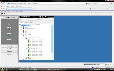
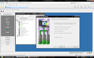
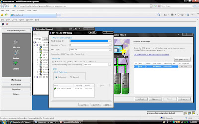
2) Once you have selected create group, it will pop up raid group creation wizard. Here you have to select so many option depending on your requirement. First select RAID Group ID. This is unique id. Then select how many disk. what it means? Let discuss for example you want to create RAID 5(3+1) then you should select 4 disk. Means there will be 4 spindle and striping will be done on 3 disk and one will be for parity. If you want to create more spindle for performance then select more disk with raid 5 configuration like you can select 8 disk for raid 5 (7+1).

Here you have option to allocate direct disk as well. then you can select disk only. Now, you have understood how to select number of disk. Next things select raid protection level.

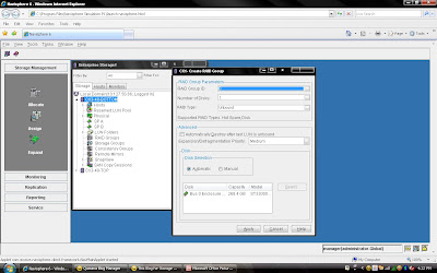
Rest, you can select default. but suppose you want to create raid group on particular disk because in same CX Frame you can have different type of disk then you can select manual then select particular disk. under disk selection tab. 
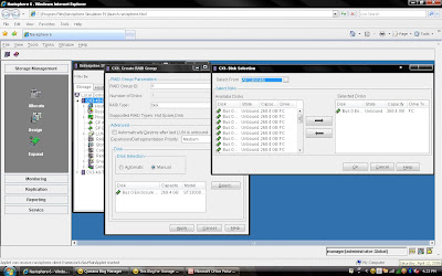
Once you have selected the all the value you can click apply. It will create RAID Group with given configuration. It will pop up message that RAID Group Created Successfully.If you want to create more group you can create using wizard otherwise click cancel.

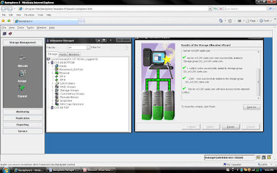
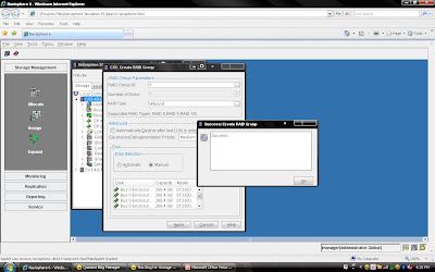
Once you have created Raid Group you can bind the lun. What is meaning of binding? Lets focus what happen when you created RAID Group. Raid Group is something like storage pool. It will create usable storage space according to number of disk you have selected and raid group type. For example we have created Raid Group 4 and it size is 1600 GB. But you want to allocate 5 LUN each LUN size would be 100 GB or any combination of size until you you exhaust the space of the raid group. So it is call binding the LUN. Means, you have taken out some space for each LUN and allocated to Host. Each LUN will have own properties but will belong to Raid Group 4. So in short when you select number of disk while creating a particular group. CLARiiON Operating System will not allow you to use same disk of some other raid protection level.
lets now bind the LUN from Raid Group 4.
Again you either select particular Raid group of CX frame or select CX Frame and Right Click and select Bind the LUN.

You have already created Raid 5 and have available space on them so select Raid 5 in Raid Type. Select Raid Group number which belong to Raid 5, for example we have created Raid Group 4 as Raid 5 level protection. Once you have selected Raid Group it will show the space available on this group.In our case we have 1608 GB space available on raid group 4. Now, I want to create 50 GB space out of 1608 GB. Once you have selected Raid Group Number you can select LUN number and properties. like LUN name, LUN Count means how many LUN you want to create with Same size. In most of case all will be default value. Generally select Default Owner as auto. let system will decide who suppose to own the device. In ClARiiON there is concept LUN ownership, at any time only one Storage Processor can own the LUN. I will cover LUN Ownership model later. Once you have selected you can click apply.

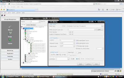
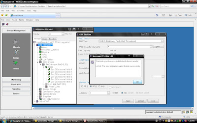
Once you have created all the LUN you can cancel that window and expand the particular raid group you can see that LUN will be listed.
This is end of CLARiiON Lab exercise II. I will be covering next class of following topic:
1) How to create Storage Group?
2) Assigned LUN to Storage Group.
3) Present LUN to Host.

I am going to demonstrate full LAB exercise of CLARiiON. If anybody interested to any specific LAB exercise please send me mail I will try to help and give LAB exercise. There are many exercise like:
1) Create RAID Group
2) Bind the LUN
3) Create Storage Group
4) Register the Host
5) Present LUN to Host
6) Create Meta LUN etc.

I will try to cover all the exercise including if you need anything extra exercise. Very Easy way to allocate the storage using Allocation wizard provided everything connected and visible to CLARiiON.

CLARiiON LAB Session -I

I am going to demonstrate LAB Exercise for Allocation Storage to Host from CX Array using Allocation Wizard of Navisphere Manager. I will be giving demo other method as well like allocating storage without wizard because some time host will not login to CX Frame. I will be discussing command line as well who are more interested in scripting.
Steps 1:
Login to Navisphere Manager ( Take any IP of any SP’s in your domain and type on browser).


You can see the all the clariion listing under each Domain.


Steps 2: Click Allocation on Left Side Menu Tree.


Steps 3: Click next once you have selected Host name (Whom you are going to present LUN)
You can select Assign LUN to this server or you can continue without assigning.


Steps 4: Select Next and Select CX frame where you want to create LUN.


Steps 5: Select Next, If you have created RAID Group It will be listed here otherwise you can create new Raid Group by selecting New Raid Group.( I will be discussing later how to create different RAID Group)


Steps 6: Select RAID Group ID and depending on Raid Group select number of disk for example if you are creating Raid 5 (3+1) then select 4 disks.
Once You have created raid group. It will list under RAID Group dialog box.Click Next and select the Number of LUN you want to create on same RAID Group. For example RAID Group created for 3+1 disk of 500 GB each disk means you can use roughly 500X4X70% GB. Now you want to create different size of each LUN on the same RAID Group


Steps 7: Once you have selected Number of LUN and Size of LUN. You can verify the configuration before you run the finish button.


Steps 8: Once you click the Finish Button you can see the status. System will create Storage Group with Server Name (You can change storage group name later) and add created LUN into storage Group.


You can verify the entire configuration by clicking storage group name:

Here we are looking at only three possible ways in which a host can be attached to a Clariion. From talking with customers in class, these seem to be the three most common ways in which the hosts are attached.
The key points to the slide are:1. The LUN, the disk space that is created on the Clariion, that will eventually be assigned to the host, is owned by one of the Storage Processors, not both.2. The host needs to be physically connected via fibre, either directly attached, or through a switch.


CONFIGURATION ONE:

In Configuration One, we see a host that has a single Host Bus Adapter (HBA), attached to a single switch. From the Switch, the cables run once to SP A, and once to SP B. The reason this host is zoned and cabled to both SPs is in the event of a LUN trespass. In Configuration One, if SP A would go down, reboot, etc...the LUN would trespass to SP B. Because the host is cabled and zoned to SP B, the host would still have access to the LUN via SP B. The problem with this configuration is the list of Single Point(s) of Failure. In the event that you would lose the HBA, the Switch, or a connection between the HBA and the Switch (the fibre, GBIC on the switch, etc...), you lose access to the Clariion, thereby losing access to your LUNs.

CONFIGURATION TWO:

In Configuration Two, we have a host with two Host Bus Adapters. HBA1 is attached to a switch, and from there, the host is zoned and cabled to SP B. HBA2 is attached to a separate switch, and from there , the host is zoned and cabled to SP A. The path from HBA2 to SP A, is shown as the "Active Path" because that is the path data will leave the host from to get to the LUN, as it is owned by SP A. The path from HBA1 to SP B, is shown as the "Standby Path" because the LUN doesn't belong to SP B. The only time that the host would use the "Standby Path" is in the event of a LUN Trespass. The advantage of using Configuration Two over Configuration One, is that there is no single point of failure.
Now, let's say we install PowerPath on the host. With PowerPath, the host has the potential to do two things. First, it allows the host to initiate the Trespass of the LUN. With PowerPath on the host, if there is a path failure (HBA gone bad, switch down, etc...), the host will issue the trespass command to the SPs, and the SPs will move the LUN, temporarily, from SP A to SP B. The second advantage of PowerPath on a host, is that it allows the host to 'Load Balance' data from the host. Again, this has nothing to do with load balancing the Clariion SPs. We will get there later. However, in Configuration Two, we only have one connection from the host to SP A. This is the only path the host has and will use to move data for this LUN.

CONFIGURATION THREE:

In Configuration Three, hardware wise, we have the same as Configuration Two. However, notice that we have a few more cables running from the switches to the Storage Processors. HBA1 is into the switch and zoned and cabled to SP A and SP B. HBA2 is into the switch and zoned and cabled to SP A and SP B. What this does now is to give HBA1 and HBA2 an 'Active Path' to SP A, and HBA1 and HBA2, 'Standby Paths' to SP B. Because of this, the Host now can route data down each active path to the Clariion, allowing the host "Load Balancing" capabilities. Also, the only time a LUN should trespass from one SP to another is if there is a Storage Processor failure. If the host were to lose HBA1, it still has HBA2 with an active path to the Clariion. The same goes for a switch failure and connection failure.

The purpose of a MetaLUN is that a Clariion can grow the size of a LUN on the ‘fly’. Let’s say that a host is running out of space on a LUN. From Navisphere, we can “Expand” a LUN by adding more LUNs to the LUN that the host has access to. To the host, we are not adding more LUNs. All the host is going to see is that the LUN has grown in size. We will explain later how to make space available to the host.There are two types of MetaLUNs, Concatenated and Striped. Each has their advantages and disadvantages, but the end result which ever you use, is that you are growing, “expanding” a LUN. A Concatenated MetaLUN is advantageous because it allows a LUN to be “grown” quickly and the space made available to the host rather quickly as well. The other advantage is that the Component LUNs that are added to the LUN assigned to the Host can be of a different RAID type and of a different size. The host writes to Cache on the Storage Processor, the Storage Processor then flushes out to the disk. With a Concatenated MetaLUN, the Clariion only writes to one LUN at a time. The Clariion is going to write to LUN 6 first. Once the Clariion fills LUN 6 with data, it then begins writing to the next LUN in the MetaLUN, which is LUN 23. The Clariion will continue writing to LUN 23 until it is full, then write to LUN 73. Because of this writing process, there is no performance gain. The Clariion is still only writing to one LUN at a time.A Striped MetaLUN is advantageous because if setup properly could enhance performance as well as protection. Let’s look first at how the MetaLUN is setup and written to, and how performance can be gained. With the Striped MetaLUN, the Clariion writes to all LUNs that make up the MetaLUN, not just one at a time. The advantage of this is more spindles/disks. The Clariion will stripe the data across all of the LUNs in the MetaLUN, and if the LUNs are on different Raid Groups, on different Buses, this will allow the application to be striped across fifteen (15) disks, and in the example above, three back-end buses of the Clariion. The workload of the application is being spread out across the back-end of the Clariion, thereby possibly increasing speed. As illustrated above, the first Data Stripe (Data Stripe 1) that the Clariion writes out to disk will go across the five disks on Raid Group 5 where LUN 6 lives. The next stripe of data (Data Stripe 2), is striped across the five disks that make up RAID Group 10 where LUN23 lives. And finally, the third stripe of data (Data Stripe 3) is striped across the five disks that make up Raid Group 20 where LUN 73 lives. And then the Clariion starts the process all over again with LUN6, then LUN 23, then LUN 73. This gives the application 15 disks to be spread across, and three buses. As for data protection, this would be similar to building a 15 disk raid group. The problem with a 15 disk raid group is that if one disk where to fail, it would take a considerable amount of time to rebuild the failed disk from the other 14 disks. Also, if there were two disks to fail in this raid group, and it was RAID 5, data would be lost. In the drawing above, each of the LUNs is on a different RAID group. That would mean that we could lose a disk in RAID Group 5, RAID Group 10, and RAID Group 20 at the same time, and still have access to the data. The other advantage of this configuration is that the rebuilds are occurring within each individual RAID Group. Rebuilding from four disks is going to be much faster than the 14 disks in a fifteen disk RAID Group.The disadvantage of using a Striped MetaLUN is that it takes time to create. When a component LUN is added to the MetaLUN, the Clariion must restripe the data across the existing LUN(s) and the new LUN. This takes time and resources of the Clariion. There may be a performance impact while a Striped MetaLUN is re-striping the data. Also, the space is not available to the host until the MetaLUN has completed re-striping the data.

What is MetaLUN?

Posted by Diwakar ADD COMMENTS

A metaLUN is a type of LUN whose maximum capacity can be the combined capacities of all the LUNs that compose it. The metaLUN feature lets you dynamically expand the capacity of a single LUN (base LUN) into a larger unit called a metaLUN. You do this by adding LUNs to the base LUN. You can also add LUNs to a metaLUN to further increase its capacity. Like a LUN, a metaLUN can belong to a Storage Group, and can participate in SnapView, MirrorView and SAN copy sessions. MetaLUNs are supported only on CX-Series storage systems.
A metaLUN may include multiple sets of LUNs and each set of LUNs is called a component. The LUNs within a component are striped together and are independent of other LUNs in the metaLUN. Any data that gets written to a metaLUN component is striped across all the LUNs in the component. The first component of any metaLUN always includes the base LUN. The number of components within a metaLUN and the number of LUNs within a component depend on the storage system type. The following table shows this relationship:
Storage System Type LUNs Per metaLUN Component Components Per metaLUN
CX700, CX600 32 16
CX500, CX400 32 8
CX300, CX200 16 8
You can expand a LUN or metaLUN in two ways — stripe expansion or concatenate expansion. A stripe expansion takes the existing data on the LUN or metaLUN you are expanding, and restripes (redistributes) it across the existing LUNs and the new LUNs you are adding. The stripe expansion may take a long time to complete. A concatenate expansion creates a new metaLUN component that includes the new expansion LUNs, and appends this component to the existing LUN or metaLUN as a single, separate, striped component. There is no restriping of data between the original storage and the new LUNs. The concatenate operation completes immediately.
During the expansion process, the host is able to process I/O to the LUN or metaLUN, and access any existing data. It does not, however, have access to any added capacity until the expansion is complete. When you can actually use the increased user capacity of the metaLUN depends on the operating system running on the servers connected to the storage system.

If you open Navisphere Manager and select any Frame/Array and click properties of Array, you will see a cache tab, which will give you cache configuration. There you need to setup configuration like LOW watermark, Hight Watermark. Did you think how CLARiiON behave on these percentage. Lets look close FLUSHING method what CLARiiON does:
There will many situation when CLARiiON Processor has to Cache Flushing to keep some free space in cache Memory.There are different size for cache memory for different series of CLARiiON.

There are three levels of flushing:
IDLE FLUSHING (LUN is not busy and user I/O continues)Idle flushing keeps some free space in write cache when I/O activity to a particular LUN is relatively low. If data immediacy were most important, idle flushing would be sufficient. If idle flushing cannot maintain free space, though, watermark flushing will be used.

WATERMARK FLUSHING The array allows the user to set two levels called watermarks: the High Water Mark (HWM) and the Low Water Mark (LWM). The base software tries to keep the number of dirty pages in cache between those two levels. If the number of dirty pages in write cache reaches 100%, forced flushing is used.

FORCED FLUSHING Forced flushes also create space for new I/Os, though they dramatically affect overall performance. When forced flushing takes place, all read and write operations are halted to clear space in the write cache. The time taken for a forced flush is very short (milliseconds), and the array may still deliver acceptable performance, even if the rate of forced flushes is in the 50 per second range.

Lets discuss about LUNz/LUN_Z in Operating System specially in CLARiiON environment. We know that what is LUN?? LUN is nothing but logical slice of disc which stands for Logical Unit Number. This terminology comes with SCSI-3 group, if you want to know more just visit www.t10.org and www.t11.org

A SCSI-3 (SCC-2) term defined as "the logical unit number that an application client uses to communicate with, configure and determine information about an SCSI storage array and the logical units attached to it. The LUN_Z value shall be zero." In the CLARiiON context, LUNz refers to a fake logical unit zero presented to the host to provide a path for host software to send configuration commands to the array when no physical logical unit zero is available to the host. When Access Logix is used on a CLARiiON array, an agent runs on the host and communicates with the storage system through either LUNz or a storage device. On a CLARiiON array, the LUNZ device is replaced when a valid LUN is assigned to the HLU LUN by the Storage Group. The agent then communicates through the storage device. The user will continue, however, to see DGC LUNz in the Device Manager.
LUNz has been implemented on CLARiiON arrays to make arrays visible to the host OS and PowerPath when no LUNs are bound on that array. When using a direct connect configuration, and there is no Navisphere Management station to talk directly to the array over IP, the LUNZ can be used as a pathway for Navisphere CLI to send Bind commands to the array.
LUNz also makes arrays visible to the host OS and PowerPath when the host’s initiators have not yet ‘logged in to the Storage Group created for the host. Without LUNz, there would be no device on the host for Navisphere Agent to push the initiator record through to the array. This is mandatory for the host to log in to the Storage Group. Once this initiator push is done, the host will be displayed as an available host to add to the Storage Group in Navisphere Manager (Navisphere Express).
LUNz should disappear once a LUN zero is bound, or when Storage Group access has been attained.To turn on the LUNz behavior on CLARiiON arrays, you must configure the "arraycommpath.

Lets first disuss what is Powerpath software. If you are familiar with EMC product and then definitelly will be using EMC Powerpath software.
Those who are new to storage world, it will interesting to know about this product as there are only few software in this category like DMP,PVLINK, LVM etc from other vendor. This sofware is one of the most robust compare to other, thats reason EMC generationg more revenue out of this Product.... .

EMC PowerPath software is Host/Server based failover software, what is that mean failover. failover can be anything like server,HBA,Fabric etc. If you have fully licenced package in your enviornment then you will have all capability. Most important not least this software got good feature like dynamic IO Loading and Automatic Failure detection which is missing in other product. Basically in short we can define that EMC PowerPath provides you to have HA configuration. EMC Powerpath slogan is like "set it and forget".

EMC PowerPath features a driver residing on the host above HBA Device Layer. This transparent componenet allows PowerPath to create Virtual(power) devices that provide failure resistant and load balanced paths to storage systems. An application needs only to reference a virt ual device while Powerpath manages path allocation to storage system.
With PowerPath, the route between server and storage system can assume a complex path. One powerpath device include as many as 32 physical I/O paths ( 16 for Clariion), with each path designated to the operating system by different name.
In most cases, the application must be reconfigured to use pseudo devices, otherwise PowerPath load balancing and path failover functionality will not be available.


The following describe whether application need to be reconfigure to use pseudo devices.
1) Windows Plateform :- No. ( Application not require to reconfigured to use Pseudo Devices )
2) AIX :- NO- For LVM, Yes, if applicaiton do not use LVM
3) HP-UX - NO
4) Solaris :- Yes, Incluing filesystem mounting tables and volume managers.
5) Linux :- Same as Solaris
if you attach new LUN to Host, powerpath automatically detect that LUN if you have exposed correctly and create device name like emcpower1c, emcpower2c etc, even when you type command on CLI like
#powermt display dev=all;
you will be able to device entry like emcpowerN.....
Hope this will help you to understand why powerpath uses pseudo devices?

What are the differences between failover modes on a CLARiiON array?

A CLARiiON array is an Active/Passive device and uses a LUN ownership model. In other words, when a LUN is bound it has a default owner, either SP-A or SP-B. I/O requests traveling to a port SP-A can only reach LUNs owned by SP-A and I/O requests traveling to a port on SP-B can only reach LUNs owned SP-B. It is necessary to have different failover methods because in certain situations a host will need to access a LUN on the non-owning SP.

The following failover modes apply:

Failover Mode 0

LUN Based Trespass Mode This failover mode is the default and works in conjunction with the Auto-trespass feature. Auto-trespass is a mode of operation that is set on a LUN by LUN basis. If Auto-Trespass is enabled on the LUN, the non-owning SP will report that the LUN exists and is available for access. The LUN will trespass to the SP where the I/O request is sent. Every time the LUN is trespassed a Unit Attention message is recorded. If Auto-trespass is disabled, the non-owning SP will report that the LUN exists but it is not available for access. If an I/O request is sent to the non-owning SP, it is rejected and the LUN’s ownership will not change.
Note: The combination of Failover Mode 0 and Auto-Trespass can be dangerous if the host is sending I/O requests to both SP-A and SP-B because the LUN will need to trespass to fulfill each request. This combination is most commonly seen on an HP-UX server using PV-Links. The Auto-trespass feature is enabled through the Initiator Type setting of HP-AutoTrespass. A host with no failover software should use the combination of Failover Mode 0 and Auto-trespass disabled.

Failover Mode 1 – Passive Not Ready Mode In this mode of operation the non-owning SP will report that all non-owned LUNs exist and are available for access. Any I/O request that is made to the non-owning SP will be rejected. A Test Unit Ready (TUR) command sent to the non-owning SP will return with a status of device not ready. This mode is similar to Failover Mode 0 with Auto-Trespass disabled. Note: This mode is most commonly used with PowerPath. To a host without PowerPath, and configured with Failover Mode 1, every passive path zoned, for example, a path to SP-B for a LUN owned by SP-A, will show to the server as Not Ready. This will show as with offline errors on a Solaris server, SC_DISK_ERR2 errors with sense bytes 0102, 0700, and 0403 on an AIX server or buffer to I/O errors on a Linux server. If PowerPath is installed, these types of messages should not occur.

Failover Mode 2 – DMP Mode In this mode of operation the non-owning SP will report that all non-owned LUNs exist and are available for access. This is similar to Failover Mode 0 with Auto-trespass Enabled. Any I/O requests made to the non-owning SP will cause the LUN to be trespassed to the SP that is receiving the request. The difference between this mode and Auto-trespass mode is that Unit Attention messages are suppressed. Note: This mode is used for some Veritas DMP configurations on some operating systems. Because of the similarities to Auto-Trespass, this mode has been known to cause “Trespass Storms.” If a server runs a script that probes all paths to the Clariion, for instance format on a Solaris server, the LUN will trespass to the non owning SP when the I/O request is sent there. If this occurs for multiple LUNs, a significant amount of trespassing will occur.

Failover Mode 3 – Passive Always Ready Mode In this mode of operation the non-owning SP will report that all non-owned LUNs exist and are available for access. Any I/O requests sent to the Non-owning SP will be rejected. This is similar to Failover Mode 1. However, any Test Unit Ready command sent from the server will return with a success message, even to the non-owning SP. Note: This mode is only used on AIX servers under very specific configuration parameters and has been developed to better handle a CLARiiON non-disruptive upgrade (NDU) when AIX servers are attached.

DMP With CLARiiON:-

CLARiiON arrays are active-passive devices that allow only one path at a time to be used for I/O. The path that is used for I/O is called the active or primary path. An alternate path (or secondary path) is configured for use in the event that the primary path fails. If the primary path to the array is lost, DMP automatically routes I/O over the secondary path or other available primary paths.

For active/passive disk arrays, VxVM uses the available primary path as long as it is accessible. DMP shifts I/O to the secondary path only when the primary path fails. This is called "failover" or "standby" mode of operation for I/O. To avoid the continuous transfer of ownership of LUNs from one controller to another, which results in a severe slowdown of I/O, do not access any LUN on other than the primary path (which could be any of four available paths on a FC4700 and CX-Series arrays).

Note: DMP does not perform load balancing across paths for active-passive disk arrays.

DMP failover functionality is supported and should attempt to limit any scripts or processes from using the passive paths to the CLARiiON array. This will prevent DMP from causing unwanted LUN trespasses.

To view potential trespasses, look at the ktrace (kt_std) information from SPcollect, messages similar the following can be seen happening with regularity.

09:07:31.995 412 820f6440 LUSM Enter LU 34 state=LU_SHUTDOWN_TRESPASS
09:07:35.970 203 820f6440 LUSM Enter LU 79 state=LU_SHUTDOWN_TRESPASS
09:07:40.028 297 820f6440 LUSM Enter LU 13 state=LU_SHUTDOWN_TRESPASS
09:07:42.840 7 820f6440 LUSM Enter LU 57 state=LU_SHUTDOWN_TRESPASS

The "Enter LU ##" is the decimal array LUN number one would see in the Navisphere Manager browser. When the messages occur, there will be no 606 trespass messages in the SP event logs. This is an indication that thetrespasses are the 'masked out' DMP trespass messages. Executing I/Os to the /dev/dsk device entry will cause this to happen.

Using the SPcollect SP_navi_getall.txt file, check the storagegroup listing to find out which hosts these LUNs belong to. Then obtain an EMCGrab/EMCReport from the affected hosts and you will need to look for a host-based process that could potentially be sending I/O down the 'passive' path. Those I/Os can be caused by performance scripts, format or devfsadm commands being run or even host monitoring software that polls all device paths.
One workaround is to install and configure EMC PowerPath. PowerPath disables the auto trespass mode and is designed to handle I/O requests properly so that the passive path is not used unless required. This will require changing the host registration parameter "failover mode" to a '1'. This failover mode is termed an "explicit mode" and it will resolve the type of trespass issues noted above.

Setting Failover Values for Initiators Connected to a Specific Storage System:

Navisphere Manager lets you edit or add storage system failover values for any or all of the HBA initiators that are connected to a storage system and displayed in the Connectivity Status dialog box for that storage system.

1. In the Enterprise Storage dialog box, navigate to the icon for the storage system whose failover properties you want to add or edit.
2. Right-click the storage system icon, and click Connectivity Status.
3. In the Connectivity Status dialog box, click Group Edit to open the Group Edit Initiators dialog box.
4. Select the initiators whose New Initiator Information values you want to add or change, and then add or edit the values in Initiator Type, ArrayCommPath and Failover Mode.
5. Click OK to save the settings and close the dialog box.
Navisphere updates the initiator records for the selected initiators, and registers any unregistered initiators.

Background Verify and Trespassing

Background Verify must be run by the SP that currently owns the LUN. Trespassing is a means of transferring current ownership of a LUN from one SP to the other. Therefore, aborting a Background Verify is part of the trespass operation – it is a necessary step.

Very simply, RAID striping is a means of improving the performance of large storage systems. For most normal PCs or laptops, files are stored in their entirety on a single disk drive, so a file must be read from start to finish and passed to the host system. With large storage arrays, disks are often organized into RAID groups that can enhance performance and protect data against disk failures. Striping is actually RAID-0; a technique that breaks up a file and interleaves its contents across all of the disks in the RAID group. This allows multiple disks to access the contents of a file simultaneously. Instead of a single disk reading a file from start to finish, striping allows one disk to read the next stripe while the previous disk is passing its stripe data to the host system -- this enhances the overall disk system performance, which is very beneficial for busy storage arrays.

Parity can be added to protect the striped data. Parity data is calculated for the stripes and placed on another disk drive. If one of the disks in the RAID group fails, the parity data can be used to rebuild the failed disk. However, multiple simultaneous disk failures may result in data loss because conventional parity only accommodates a single disk failure.

RAID striping
The performance impact of RAID striping at the array and operating system level.
RAID striping or concatenation: Which has better performance?
Designing storage for performance is a very esoteric effort by nature. There are quite a few variables that need to be taken into account.
RAID-50: RAID-5 with suspenders
RAID-50 combines striping with distributed parity for higher reliability and data transfer capabilities.
RAID-53: RAID by any other name
RAID-53 has a higher transaction rate than RAID-3, and offers all the protection of RAID-10, but there are disadvantages as well.
RAID-10 and RAID-01: Same or different?
The difference between RAID-10 and RAID-01 is explained.
RAID explained
RAID, or redundant array of independent disks, can make many smaller disks appear as one large disk to a server for better performance and higher availability.

About Me

My photo
Sr. Solutions Architect; Expertise: - Cloud Design & Architect - Data Center Consolidation - DC/Storage Virtualization - Technology Refresh - Data Migration - SAN Refresh - Data Center Architecture More info:- diwakar@emcstorageinfo.com
Blog Disclaimer: “The opinions expressed here are my personal opinions. Content published here is not read or approved in advance by EMC and does not necessarily reflect the views and opinions of EMC.”
EMC Storage Product Knowledge Sharing